INSTALLATION AND OPERATION MANUAL
CR3 CR5, and CR7 Charging Racks Charging Rack Installation
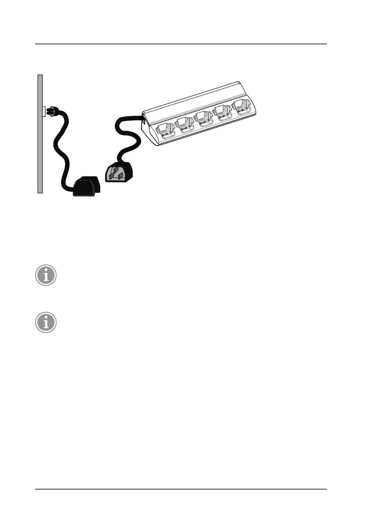
Figure 5. Example of CR7- AAAA Charging Rack with IEC C14 connector and an extension cord with an IEC
C13 connector
For the Advanced Charging Rack, connect the communication cable when required.
Installation Test
1. Connect the mains power supply cord to the wall socket.
2. The LED on the front of the charger should light up.
The LED is disabled on the Basic Charging Rack and will not light up. Put a handset into a charging
slot and check if the handset LED lights up.
Power Supply by Fixed Connection
If the Charging Rack shall be connected with a fixed connection, the AC connection must be done
by a authorized electrician.
It is possible to use any of the two AC terminal blocks for AC input. Consequently, the unused terminal
block may be used to connect the next Charging Rack or battery pack charger.
The Power Supply module connects to 100-240VAC/0.7A 50/60 Hz. When working with the units the mains
power supply cable must always be disconnected. The safety covers must be mounted on top of the power
supply terminal blocks to prevent hazardous situations, like electric chock.
TD 92480EN / 30 October 2020 / Ver. L 8