DBT12/15/24 Operations Manual....21
5.2. ELECTRICAL INSTALLATION
This procedure assumes the physical installation of the unit has been completed. It is the user’s
responsibility to provide input service overcurrent protection and disconnect means.
It is recommended that connections be made to the distribution bus through a manually operated
disconnect device such as a molded case switch or circuit breaker (rated for the total system
amperage) to ease disconnection and provide a safe servicing environment in the event of unit
failure.
Conductors should be sized for the maximum continuous currents listed in Section 4.1.1.
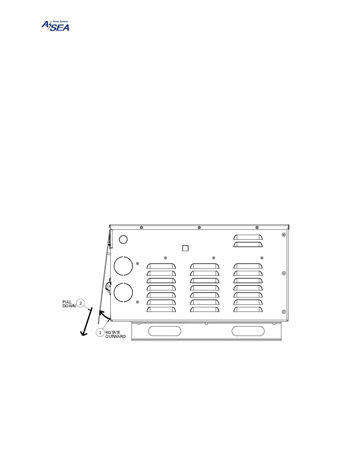
All power wiring requires the removal of the front cover. This cover is secured with 5 ea. 10-32
× 1/4" stainless steel screws. Set the input circuit breaker to the OFF position. Remove the
front cover by first tilting its bottom side outward so that it is no longer resting on the circuit
breaker, then lowering it past the lip of the top cover. Take caution of the ribbon cable connected
to the display.
Figure 7: Front Cover Removal
Prepare the power cables by removing the outer cable jacket approximately 6" (15 cm). Strip
back the insulation of all wires exposing ½" (1.25 cm) of bare conductor. Insert the prepared
cable and strain relief assembly into the appropriate hole in the chassis. Insert the wire ends into
the terminal blocks and tighten.