DBT12/15/24 Operations Manual....51
8.4. BYPASS AND 1:1 MODES
The Bypass mode allows the DBT12/15/24 to temporarily operate under very unstable shore power
conditions or while troubleshooting installations with extremely high load spikes. In this mode
most advanced functionality of the DBT12/15/24 including voltage boosting and overvoltage or
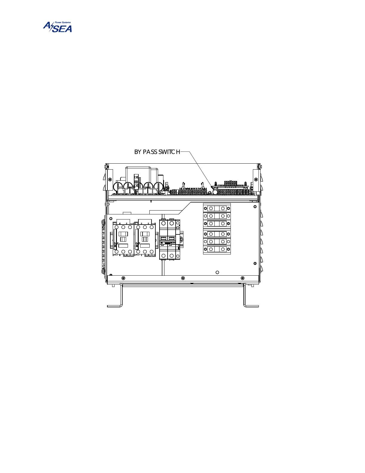
overload protection is disabled. A push-in / push-out Bypass switch located near the center of
the control PCBA, as shown in Figure 20, is used to select normal operation in the out position or
Bypass mode in the in position. The switch lights solid green when the DBT12/15/24 is operating
normally and solid yellow in Bypass mode.
Figure 20: Bypass Switch Location.
If a Boost 1 or a Boost 2 fault is detected during self-test, voltage boosting is disabled and the
DBT12/15/24 only runs in 1:1 mode. In this case the bypass switch flashes green.
8.5. GATHERING DATA
If a problem is being encountered by the unit, carefully record the fault and warning messages
listed before removing power. When calling an authorized service center or the factory for
assistance, please have the above mentioned information handy along with the unit model, serial
number, and software version.