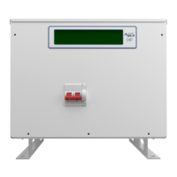
DBT12/15/24 Operations Manual....24
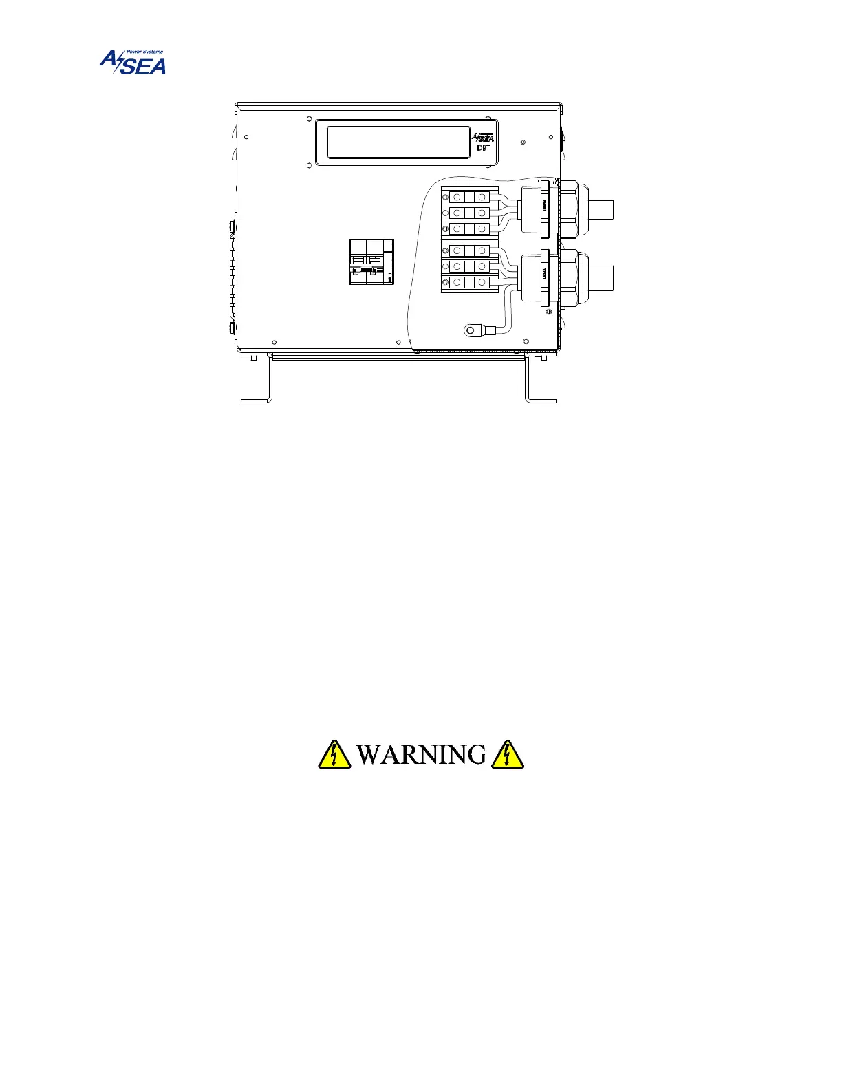
Figure 10: Power Cables Entering from the Right Side
Cord grip connectors with water sealing bushings and strain relief can be used to secure the cables
coming in from the right side of the unit. Cord grip connectors are not supplied. The
recommended cord grip connector for 0.87" (22 mm) to 1.26" (32 mm) diameter cables is Sealcon
CD36NA-GY with locking nut NN-36-ST.
5.2.2. Grounding
The unit chassis ground MUST be connected to the ship’s hull or common ground point via the
stud below the two terminal blocks, labeled with the ground symbol. Failure to do so may create
conditions that may in turn cause injury or death to operators; failure to do so will also result in
the voiding of the equipment warranty.
THE UNIT ISOLATES THE SHIP POWER FROM THE SHORE POWER
AND EQUIPMENT (SAFETY) GROUNDS SIMILAR TO AN ISOLATION
TRANSFORMER. THE INSTALLER MUST RE-ESTABLISH THE
GROUND REFERENCE FOR THE EQUIPMENT AT TIME OF
INSTALLATION. NEUTRAL AND EQUIPMENT (SAFETY) GROUND
ARE TO BE CONNECTED PER THE APPROPRIATE CLASS
STANDARD.