DBT12/15/24 Operations Manual....29
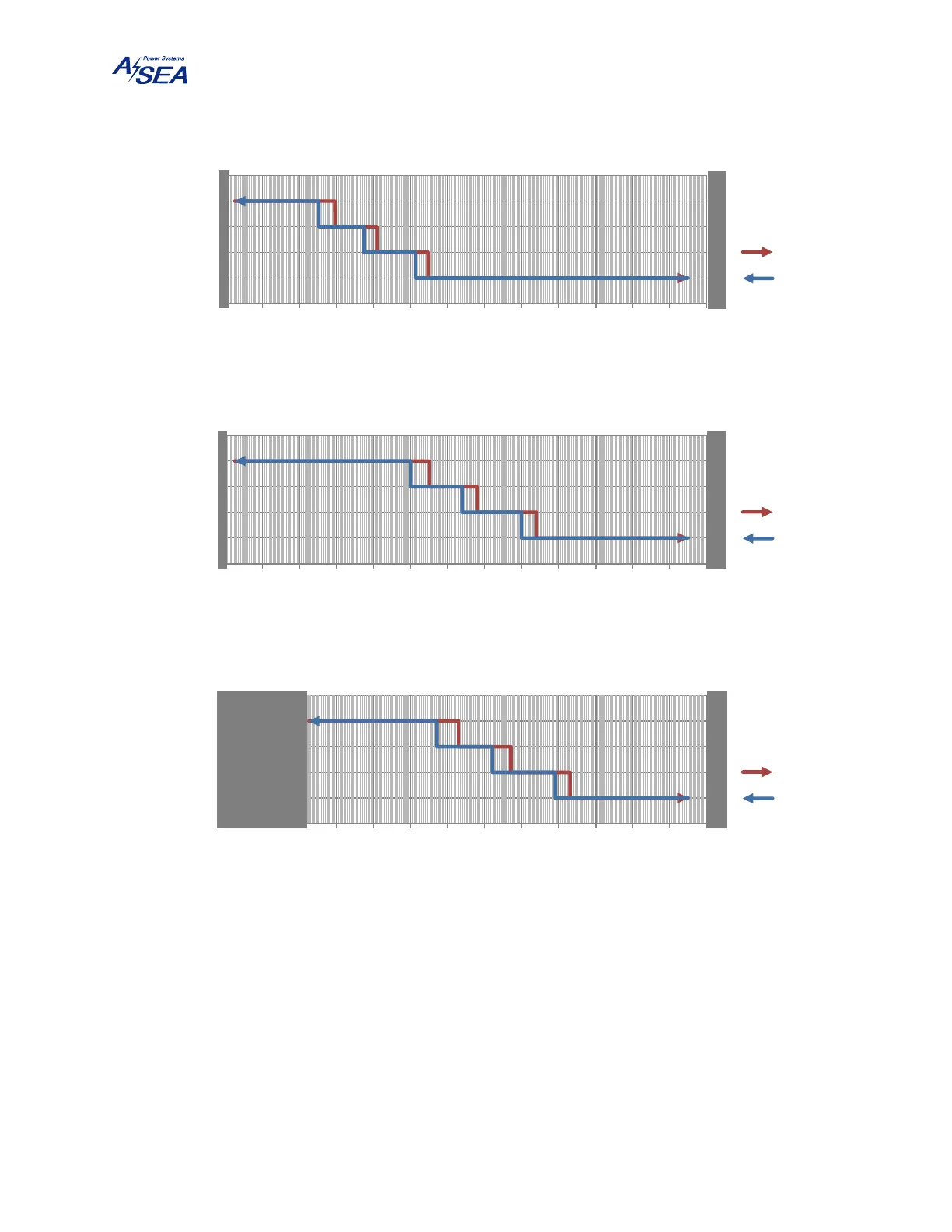
Figure 12: Voltage Chart Indicating the Gain Selection Hysteresis (continued)
6.3. TURN-OFF PROCEDURE
Turn the circuit breaker to the OFF position. The unit will open its internal shore and ship power
contactors, and then power off.
400:230
BOOST1
BOOST2
BOOST3
280 300 320 340 360 380 400 420 440 460 480 500 520 540
Gain
Shore Voltage (V
RMS
)
DBT24 400 V
RMS
Range
Vin ↗
Vin ↘
F
A
U
L
T
F
A
U
L
T
2:1
BOOST1
BOOST2
BOOST3
280 300 320 340 360 380 400 420 440 460 480 500 520 540
Gain
Shore Voltage (V
RMS
)
DBT24 480 V
RMS
Range
Vin ↗
Vin ↘
F
A
U
L
T
F
A
U
L
T
2:1
BOOST1
BOOST2
BOOST3
280 300 320 340 360 380 400 420 440 460 480 500 520 540
Gain
Shore Voltage (V
RMS
)
DBT24-60Hz High-Range
Vin ↗
Vin ↘
F
A
U
L
T
F
A
U
L
T