DBT12/15/24 Operations Manual....28
6.2. OPERATION
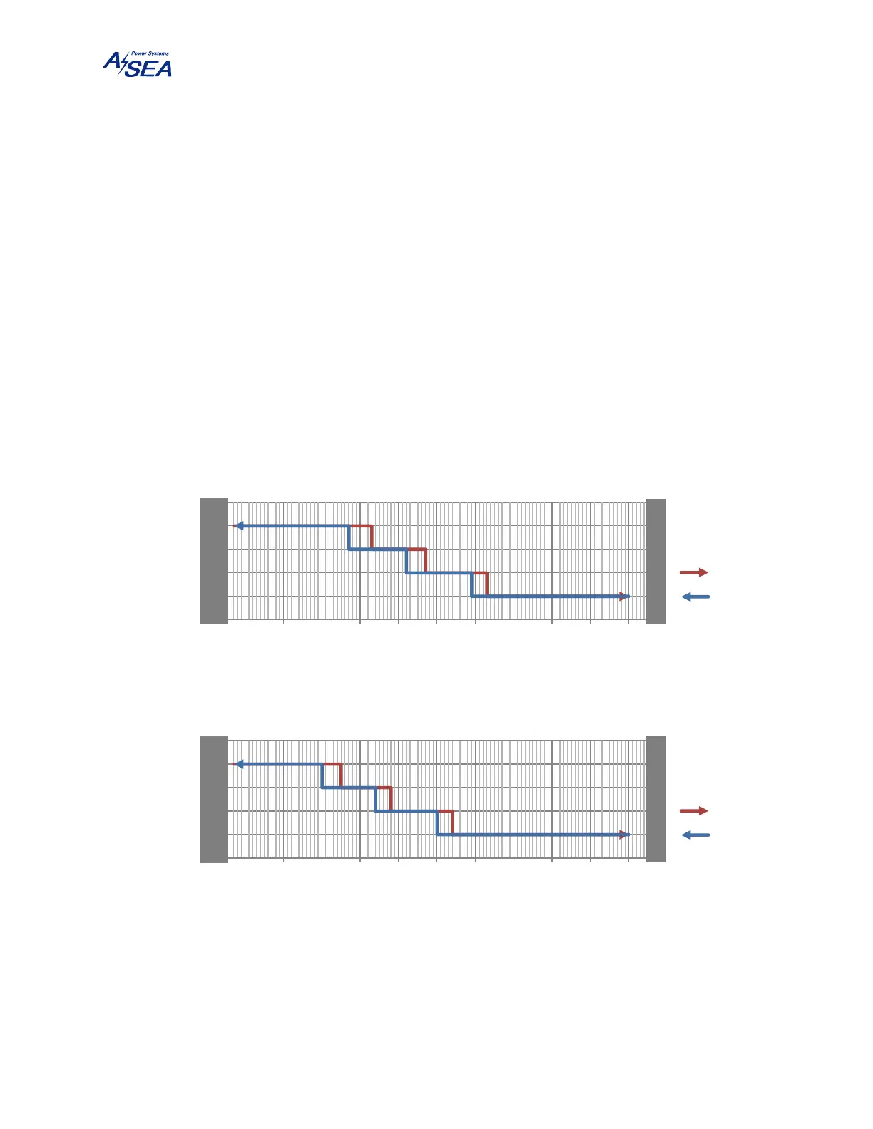
The DBT24 and the DBT24-60Hz select once at power-up low- or high-range shore voltage
operation. The DBT24 additionally selects 400 V
RMS
or 480 V
RMS
high-range shore voltage
operation.
After power-up the DBT12/15/24 constantly monitors the shore voltage and selects an appropriate
gain according to the following logic:
a. When the shore voltage decreases, the unit will target a higher gain according to Figure 12.
b. When the shore voltage increases, the unit will target a lower gain according to Figure 12.
c. A gain change will take place after the target gain has been continuously higher or
continuously lower than the current gain for a time period of 15 minutes, and only if
no overload condition exists.
Figure 12: Voltage Chart Indicating the Gain Selection Hysteresis
1:1
BOOST1
BOOST2
BOOST3
160 170 180 190 200 210 220 230 240 250 260 270
Gain
Shore Voltage (V
RMS
)
DBT12 / DBT24-60Hz Low-Range
Vin ↗
Vin ↘
F
A
U
L
T
F
A
U
L
T
1:1
BOOST1
BOOST2
BOOST3
160 170 180 190 200 210 220 230 240 250 260 270
Gain
Shore Voltage (V
RMS
)
DBT15 / DBT24 Low-Range
Vin ↗
Vin ↘
F
A
U
L
T
F
A
U
L
T