22
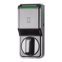
Lock self test LED indication
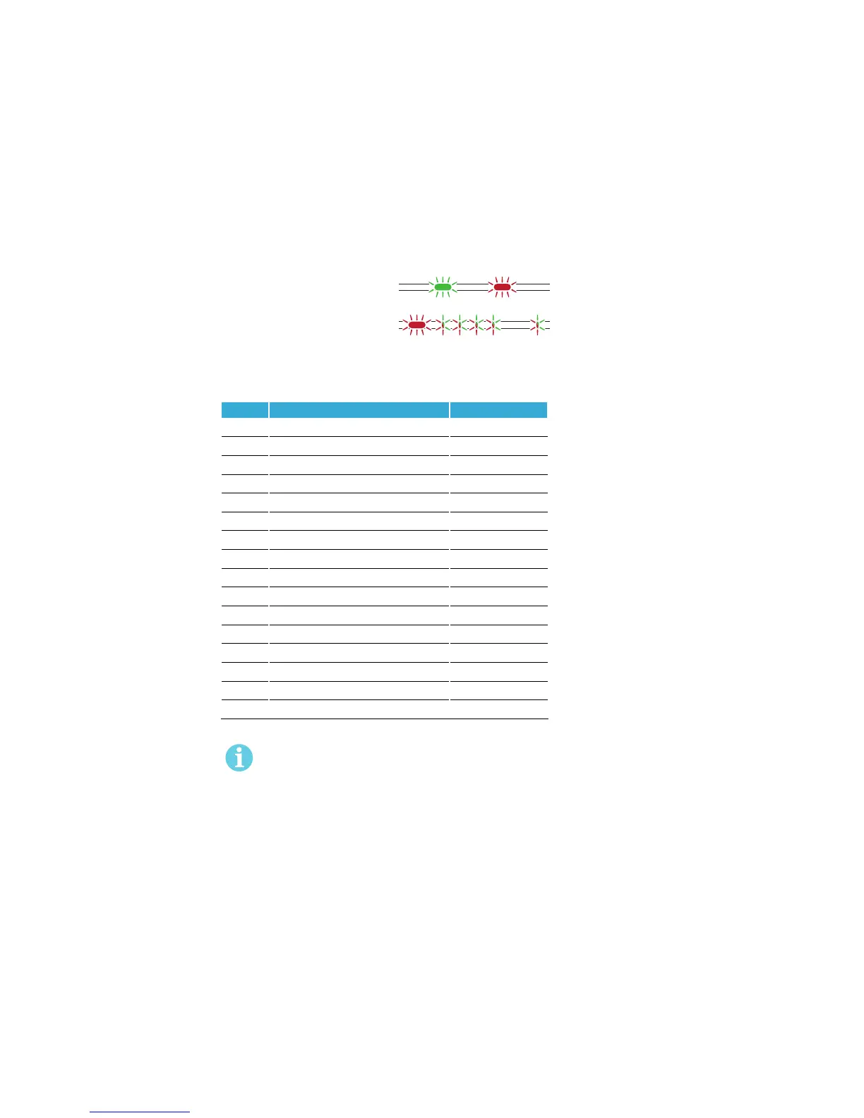
After replacing the battery, a Power on Self Test (POST) is performed. The result is indicated using a
series of red and green LED flashes as is described by the figure below:
One red, one green flash
(1 second)
POST Successful
One red flash followed by 16
red or green flashes (.5 second)
Failure during POST
...
The first flash is always red. If the POST fail, the color of the 16 trailing flashes indicate the status of
each individual test as described by the following table:
Blink Meaning if red Code in event log
2 Main board firmware corrupt 0x0001
3 Override list corrupt 0x0002
4 Production data corrupt 0x0004
5 Security data corrupt 0x0008
6 Configuration data corrupt 0x0010
7 Load Circuit Error 0x0020
8 Configuration data corrupt 2 0x0040
9 Secure Area Encryption Key error 0x0080
10 Secure Area Motor error 0x0100
11 Secure area communication error 0x0200
12 Secure area memory corrupt 0x0400
13 Secure area sensor or motor error 0x0800
14 Radio modem communication error 0x1000
15 Radio modem memory corrupt 0x2000
16 Radio modem configuration error 0x4000
17 Radio modem RF circuit error 0x8000
If the battery is not accepted as new after a power on reset, no POST is performed, instead
the 10 quick red flashes used to indicate “Error in lock” are shown.
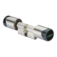
Figure 7. Lock POST LED
indication