43
ENEN
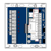
Mounting
· The supply lines must be routed from below through the cable bushings in the
housing bottom (Fig. 2–
1 ).
· The supply lines must be routed and fixed behind or next to the control termi-
nal. Ensure that the supply lines are not damaged by the fastening screws of the
control terminal.
· The cables must be routed between the webs on the housing base and the
fastening domes for the housing cover then fixed in this position with the strain
relief clamps (–
2 ).
· The space between the webs on the housing base must remain free.
· Use suitable cable ties to fasten the wires (–
3 ).
· In the case of model 1338, only the power supply line is routed through the left
cable inlet. The right cable inlet is used for all control cables.
Cable selection
The maximum length of the control cables is 300m and the maximum length of
the cables to the locking part is 100m.
The conductor cross-section must be selected so that the voltage on the locking
part is no more than 10% below the specified rated operating voltage of the
locking part at full load and take into account all other losses, such as the voltage
drop on the supply line.
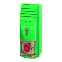
Connectible locking elements
The connection of locking elements is listed in documentation D00470. The
number depends on the specified rated current consumption for external
consumers. Permissible device combinations in accordance with EltVTR can be
found in the current test certificate.
 Loading...