Do you have a question about the Assa Abloy EffEff 1338-14 and is the answer not in the manual?
Manual for qualified electricians on safe installation and operation of the device.
Explanation of danger, warning, caution, important, and note symbols used in the manual.
Warning about contacting live parts; device only to be opened by a certified electrician.
Safety features are essential for EltVTR conformity; no unauthorized changes.
Critical for centrally controlled escape doors; requires approval and manned station.
Commissioning must be done by qualified person; training available.
Owner responsible for correct installation and testing; yearly expert testing required.
Compliance with regulations is mandatory; training available.
Repairs must be done by qualified persons if device is not operating normally or shows damage.
Electrical locking devices for escape routes in commercial applications, tested per EltVTR.
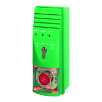
Product is only suitable for surface-mounted wall mounting.
Installation by electrician with escape-door control system expertise required.
Device must be disconnectable from power supply via an accessible energy-isolation device.
Usage must be coordinated with inspection authorities for safety concepts and door modifications.
Controls and monitors a single escape door, integrating all control devices internally.
Details differences between Model 1338-20 and Model 1338-14.
Features integrated mains adapter for power, supports stand-alone or bus operation.
Designed for stand-alone operation, same functionality as 1338-20 but without bus support.
Lists features like stand-alone mode, emergency button unlock, external/internal release, status signals.
Describes Mode 1 (stand-alone) and Mode 2 (bus participant) for 1338-20 models.
Emergency push-button height 850-1200 mm from floor; consult local ordinances.
Terminal for surface-mounted wall mounting near escape door; cable routing and fastening.
Details on routing supply and control lines through bushings, fixing wires, and strain relief.
Maximum cable lengths (300m control, 100m locking) and conductor cross-section for voltage drop.
Connection details depend on current consumption; permissible combinations per EltVTR.
Profile half cylinder design 90° left, 30-35 mm length can be used.
Detailed instructions for switching off power, removing cover, disconnecting cable, and replacing cylinder.
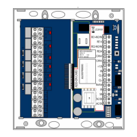
Schematic showing power supply, control board, emergency switch, and external connections.
How to connect the fire alarm system according to DIN EN 13637:2015.
Configuration of pre-alarm and permanent release via jumpers.
Explains DIP switch S4 functions related to door opening monitoring and pre-alarm.
How DIP switch S4 configures stand-alone (Mode 1) or bus operation (Mode 2).
Details functions like door opening time monitoring, temporary/permanent release, and fire alarm signal.
Sets temporary and permanent release duration (11-176 seconds).
Sets pre-alarm duration (Mode 1) or participant address (Mode 2).
Sets alarm duration (Mode 1) or participant address (Mode 2).
Controls illumination of the EMERGENCY-OPEN switch (off, green, red).
Connecting a DCB controller 970-TSBC via a two-wire bus line to Data and GND terminals.
Assigning unique addresses to components on the data bus using rotary switches S3 and S2.
Defines the address range (e.g., 0-15, 16-31) based on the switch position.
Adds an offset to the address range to set individual component addresses.
Check elements, electrical connections, and ensure proper installation and function by specialists.
System automatically queries inputs and determines status upon power-up or failure.
Unlocking the door for a set time using switch S1; indicated by green LED flashing.
Temporary release activated by key pushbutton, terminals 11/12 or 17/20.
Temporary release via key switch can be deactivated by DIP switch S4-2.
Temporary release ends when the door is opened and closed again.
Pre-alarm triggered if door stays open; alarm requires acknowledgment.
Restarting release time with each key press on external buttons.
Door permanently unlocked via closed contact; green LED stays on.
Activated via key pushbutton, terminals 19, 9/10, 11/12, control panel 1332, or DCB controller.
Jumper activation for key pushbutton release; DIP switch S4-3 for immediate or delayed release.
Temporary or permanent release can be interrupted to lock the door; red LED indicates locked state.
Locking via key pushbutton or terminals 17/20; cannot lock if alarm is present.
Settings for temporary release, pre-alarm, and acoustic alarm durations via rotary switches.
Temporary release and pre-alarm durations set via DCB controller.
Alarm must be acknowledged when door is closed; unlocking stops alarm.
Warns door must be closed after temporary release; acoustic signal volume reduced.
Pre-alarm ends by closing door, activating temporary, or permanent release.
Connect fire alarm system to terminals 13/14; door unlocks immediately.
Terminals 13/14 need a jumper if no fire alarm system connected.
Door unlocked (except tampering), acoustic signal active, relay closed, LEDs indicate alarm.
Distinguishes between danger alarm, tamper alarm, and alarm after pre-alarm.
Triggered by EMERGENCY-OPEN switch, fire alarm, or unsuccessful locking attempt.
Triggered by opening device; door remains locked; cannot be reset if damaged.
Push key pushbutton to unlock; acoustic alarm ends, LEDs change.
Query alarm cause using key switch; display relevant LED signals.
Remove alarm cause (e.g., close door); green LED permanently lit, alarm memory cleared.
Device requires no maintenance; faulty units must be sent for inspection.
Building operators must ensure annual inspection by technical specialists.
CE marking, EltVTR compliance, and declaration of conformity information.
Rated operating voltage (230V AC), current consumption (155 mA), safety fuse.
Rated operating voltage (24V DC), current consumption, safety fuses, relay capacity.
Dimensions, emergency switching element, LEDs, protection category (IP20), ambient temperature.
Statutory warranty periods and terms of sale apply.
Dispose as electronic scrap at collection points; follow environmental regulations.
Latest information available on the website assaabloyopeningsolutions.de.
Document correct fitting and installation of all components using the test book.
Verify red LEDs, secure locking, and emergency button function.
Test alarm system activation, red LEDs, secure locking.
Verify door release, opening effort, green LEDs, and acoustic alarm during permanent release.
Test hazard warning system if connected, including door release and LED indications.
| Model Number | 1338-14 |
|---|---|
| Brand | Assa Abloy EffEff |
| Operating Voltage | 12/24 V DC |
| Fail-Secure/Fail-Safe | Fail-Safe |
| Adjustable Latch | Yes |
| Latch adjustment | 3 mm |
| Housing Material | Metal |
| Suitable for | Doors |