EasyManua.ls Logo

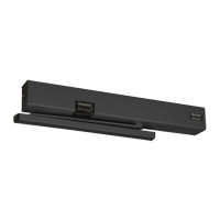
Assa Abloy Norton 7200 Series User Manual

Assa Abloy Norton 7200 Series
16 pages
To Next Page IconTo Next Page
Page #1 background imageLoading...
Page #1 background image
Copyright © 2010, 2014 Yale Security Inc., an ASSA ABLOY Group company. All rights reserved.
Reproduction in whole or in part without the express written permission of Yale Security Inc. is prohibited.
ASSA ABLOY
80-9372-0100-020 (02-14)
1
Requirements:
Units are handed. Hand of unit and hand of door must be the same.
All dimensions shown in inches (mm).
Door must be hung on ball bearing butt hinges or 3/4" (19) offset pivots.
Door thickness must be 1-3/4" (44) to 2-1/4" (64).
Door must swing freely through the entire opening and closing cycle before beginning the installation procedure.
Frame face must be a minimum of 2" (51).
Ceiling clearance must be a minimum of 3 -1/2" (89) for push side application or 4" (102) for pull side application. See pages
2 and 7 for templates.
Power input to unit must be of the same voltage as that stated on the unit.
Unit to be mounted on interior of building in dry environment, maximum humidity of 95%.
See NFPA70 for wiring requirements and NFPA72 for alarm system requirements.
Pull Side Applications with Slide Track
(7210, 7250)
(see page 7 for template)
Push Side Applications with Double Lever Arms
(7220, 7230)
(see page 2 for template)
Item No. Description
1 Track (Pull Side)
2 Cover
3 Track Arm (Pull Side)
4 Double Lever Arm (Push Side)
• Allen wrench set (inch)
• Flat blade screwdriver (potentiometer &
terminal size)
• Screwdriver (Phillips size 2)
Tape ruler
• Power drill
• Center punch
Wire stripper
Tools required:
Use screw pack and hardware provided to mount operator.
3
1
2
4
Table of Contents:
Push Side Template....................2
Push Side Installation..............2-4
Closer Adjustments.....................5
Hold Open Position Adj...............6
Pull Side Template......................7
Pull Side Installation.................7-9
Closer Adjustments...................10
Hold Open Position Adj.............11
Non-Detectored Electrical.........12
Detectored Electrical.................13
RF Unit Electrical.................14-15
Troubleshooting.........................15
General Information..................16
ASSA ABLOY
7200 Series Multi-Point Hold Open
Installation and Instruction Manual
Question and Answer IconNeed help?

Do you have a question about the Assa Abloy Norton 7200 Series and is the answer not in the manual?

Assa Abloy Norton 7200 Series Specifications

General IconGeneral
Series7200 Series
MountingSurface
SizeVaries by model
HandingNon-handed
ComplianceUL Listed
Armature Plate MaterialSteel
Mounting OptionsSurface

Summary

Push Side Applications with Double Lever Arms

Prepare Frame

Instructions for preparing the door frame for closer mounting.

Closer Mounting

Steps for mounting the closer body to the prepared frame.

Operator Mounting

Procedure for hanging the closer body and securing it to the frame.

Closer Mounting (Back Plate)

Installing remaining mounting screws for the closer back plate.

Arm Shoe Mounting

Attaching the closer arm shoe to the door face.

Attach Arm

Connecting the closer arm to the operator and securing it.

Preload Closer Spring

Setting the initial spring tension by positioning the arm.

Closer Spring Adjustment

Adjusting the closing force of the door closer.

Closer Adjustments

Fine-tuning sweep, latch, backcheck, and hold open positions.

Electrical Connections

Details for connecting electrical components for various unit types.

Selective Hold Open Cam Adjustment

Adjusting the cam to set the desired hold open angle.

Attach Cover

Securing the cover to the closer unit using provided screws.

Pull Side Applications with Slide Track

Prepare Frame

Instructions for preparing the door frame for track mount installation.

Closer Mounting

Steps for mounting the closer body to the prepared frame.

Closer Mounting (Continued)

Hanging the closer body and securing it to the frame.

Closer Mounting (Back Plate)

Installing remaining mounting screws for the closer back plate.

Arm Mounting

Mounting the closer arm to the pinion square.

Attach Arm

Securing the closer arm to the slider assembly with provided hardware.

Mount Track

Installing the track onto the door frame or header.

Connect Arm to Track

Connecting the closer arm to the slider assembly in the track.

Closer Spring Adjustment

Adjusting the closing force for consistent door closure.

Closer Adjustments

Fine-tuning sweep, latch, backcheck, and hold open ranges.

Electrical Connections

Details for connecting electrical components for various unit types.

Selective Hold Open Cam Adjustment

Adjusting the cam to set the desired hold open angle.

Attach Cover

Securing the cover to the closer unit using provided screws.

Non-Detected Electrical Connections

Surface Mount Power Input

Instructions for surface mounting power input for non-detected units.

120V AC Input Wiring

Wiring diagram for 120V AC power input connections.

24V DC Input Wiring

Wiring diagram for 24V DC power input connections.

Smoke Detector Electrical Connections

Surface Mount Power Input

Instructions for surface mounting power input for smoke detector units.

120V AC Input Wiring

Wiring diagram for 120V AC power input connections.

24V AC/DC Input Wiring

Wiring diagram for 24V AC/DC power input connections.

RF Remote Receiver Units Electrical Connections

Surface Mount Power Input

Instructions for surface mounting power input for RF receiver units.

120V AC Input Wiring

Wiring diagram for 120V AC power input connections.

24V AC/DC Input Wiring

Wiring diagram for 24V AC/DC power input connections.

Programming RF Remote Receiver Units

DIP Switch Settings

Configuration options for DIP switches on the RF receiver.

Hand Held Configuration

Steps for programming transmitters using a handheld device.

Push Plate Configuration

Instructions for configuring push plates with the RF transmitter.

Removing Transmitter Code

Procedure for deleting transmitter codes from the receiver.

Troubleshooting RF Units

Common issues and solutions for RF unit operation.

General Information

MPSO and MPDO Closer Overview

Diagrams illustrating the components of MPSO and MPDO closer units.

Parts Included with Pull Side or Double Egress

List and diagrams of parts included for pull side or double egress installations.

Parts Included with Push Side

List and diagrams of parts included for push side installations.

Preparation for Fasteners

Specifications and drill sizes for fasteners used in door closer installation.

Certifications

List of product certifications for safety and compliance.

Related product manuals