65 of 108
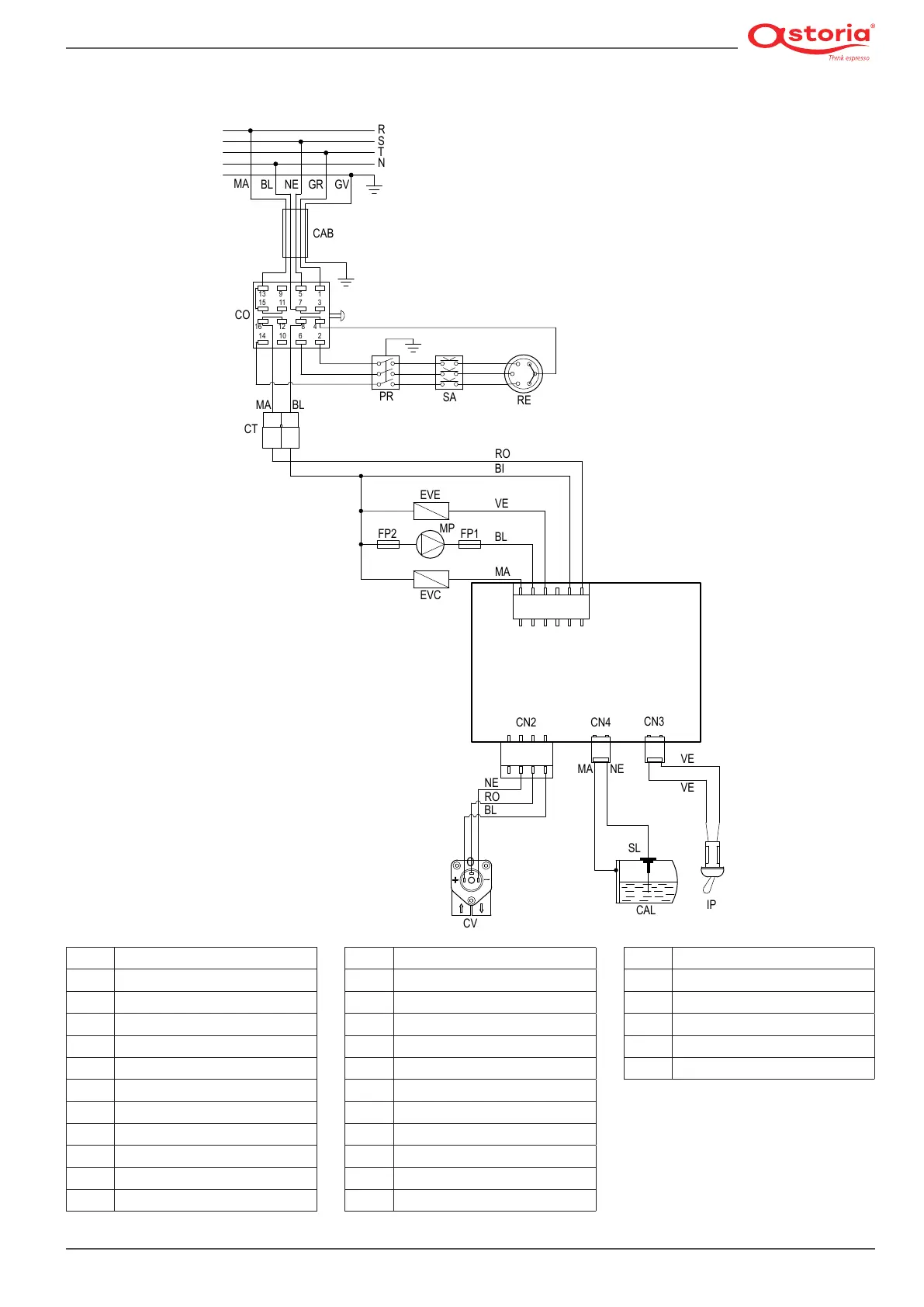
13.5.2 Wiring diagram code 18371010 - 18371011 *JUNIOR*
BI
White
BL
Blue
CAB
Power cable
CAL
Heating unit
CM
Membrane connection
CN1
Power supply and services outputs
CN2
Dosing device output
CN3
Programming switch
CN4
Heating unit level
CO
Power switch
CT
Power supply connector
CV
Volumetric counter
RE
Heating element
RO
Red
SA
Safety heating element
SL
Heating unit level probe
TR
Transformer
VE
Green
(
*
) Fuses for UL versions where a plug with
a capacity greater than 30 A is installed
EVC
Heating unit lling solenoid valve
EVE
Dispensing solenoid valve
FP1(*)
UL (OPD) Motor pump fuse
FP2(*)
UL (OPD) Fuse for 230 V
GR
Grey
GV
Yellow-green
IP
Programming switch
LA
Indicator light
MA
Brown
MP
Motor pump
NE
Black
PR
Pressure switch