66 of 108
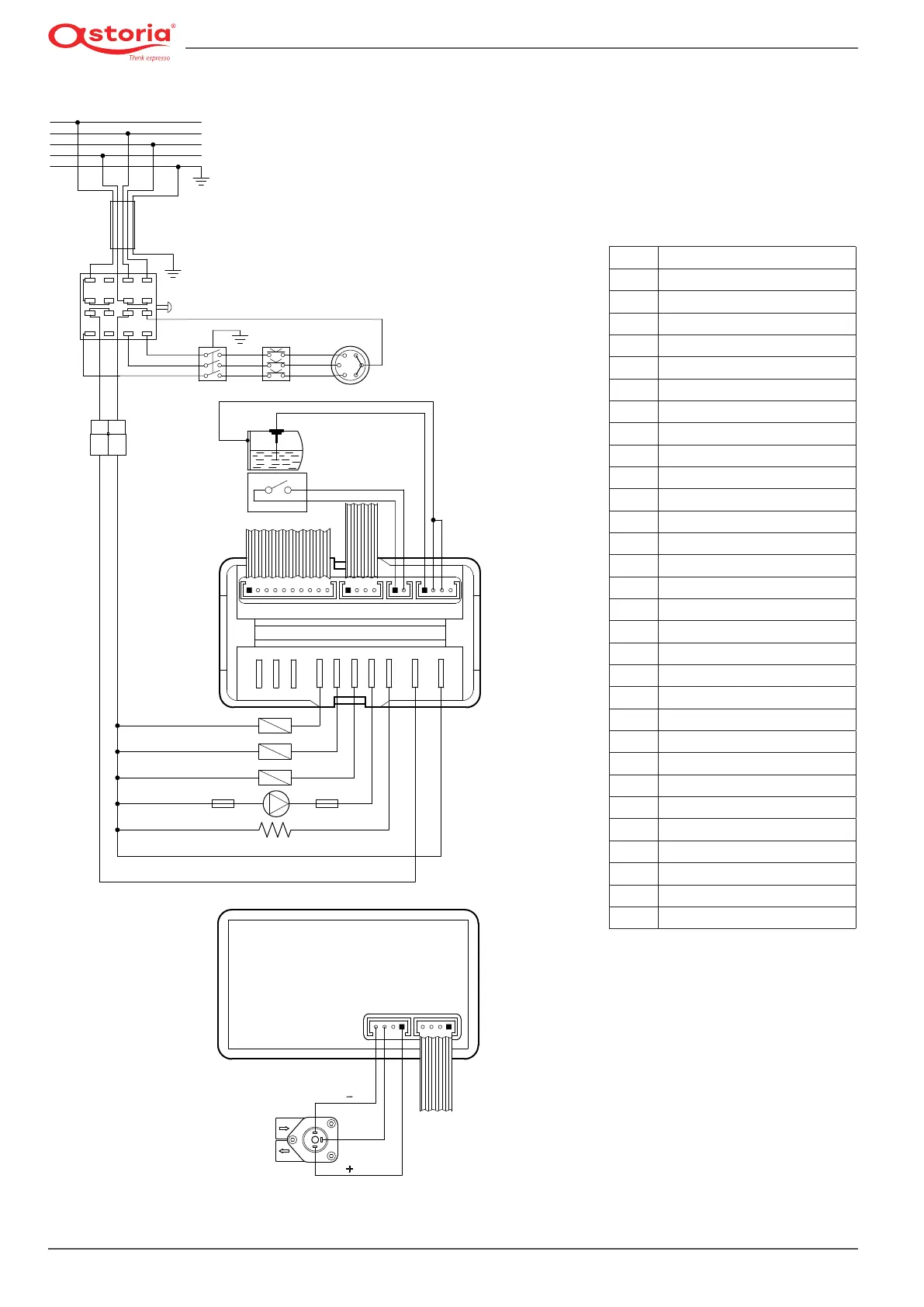
13.5.3 Wiring diagram code 18090065 - 18090066 *JUNIOR*
Back
Front
O
FA1
FA2
FA4
FA5
FA3
FA6
FA7
CN1 CN2 CN3 CN4
CN7CN6
13 9 5
1
3
71115
16 12 8
4
2
610
14
FP1FP2
CT
PR
SA
CO
RE
R
S
T
N
MA
BL NE GR GV
CAB
MA
BL
SL
CAL
PR
EVG
EVT
EVC
MP
RIS
CV
BI
White
BL
Blue
CAB
Power cable
CAL
Heating unit
CN1
Pushbutton panel connection
CN2
Tea button connection
CN3
Pressure switch connection
CN4
Heating unit level connection
CN6
Volumetric counter connection
CN7
RS232 serial network connection
CO
Power switch
CT
Power supply connector
CV
Volumetric counter
EVC
Heating unit lling solenoid valve
EVG
Group solenoid valve
EVT
Tea solenoid valve
FP1(*)
UL (OPD) Motor pump fuse
FP2(*)
UL (OPD) Fuse for 230 V
GR
Grey
GV
Yellow-green
LA
Indicator light
MA
Brown
MP
Motor pump
NE
Black
PR
Pressure switch
RE
Heating element
RIS
Heating
RO
Red
SA
Safety heating element
SL
Heating unit level probe
VE
Green
(
*
) Fuses for UL versions where a plug with
a capacity greater than 30 A is installed