Astraada DRV-24 frequency inverters Function Parameters
34
Detailed instruction of parameters
percentage of rated current of inverter. The
bigger the DC braking current is, the greater the
braking torque is.
DC braking time: the retention time of DC
braking. If the time is 0, the DC braking is
invalid. The inverter will stop at the set
deceleration time.
Setting range of P01.09: 0.00Hz~P00.03
(the Max. frequency)
Setting range of P01.10: 0.00~50.00s
Setting range of P01.11: 0.0~100.0%
Setting range of P01.12: 0.00~50.00s
Dead time
of FWD/REV
rotation
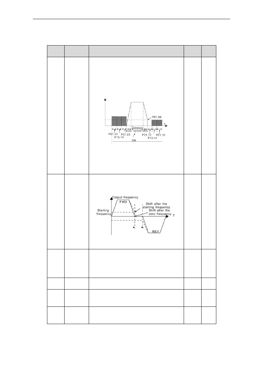
During the procedure of switching FWD/REV
rotation, set the threshold by P01.14, which is
as the table below:
Setting range: 0.0~3600.0s
Switching
between
FWD/REV
rotation
Set the threshold point of the inverter:
0:Switch after zero frequency
1:Switch after the starting frequency
2: Switch after the speed reach P01.15 and
delay for P01.24
Detection of
stopping
speed
0: Detect at the setting speed
1: Detect at the feedback speed(only valid for
vector control)
Detection
time of the
feedback
When P01.16=1, the actual output frequency of
the inverter is less than or equal to P01.15 and
is detected during the time set by P01.17, the
 Loading...