Viron eQ Salt Chlorinator With Bluetooth | Installation and Operation Manual
Page 7
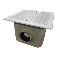
Section 3. Plumbing
HEATER
SENSOR LOCATION
FILTER
PUMP
POOL/SPA
3 WAY VALVE
SPA RETURN
POOL RETURN
CELL
CONTROLLER
CHEMICAL
DRUM
INJECTION POINT
Figure 3. Viron eQ Installation and Plumbing
The cell must be plumbed in a position that is
accessible for maintenance and within 1.5 m of
the controller. The cell should be the last piece of
equipment in the circulation system. The cell must
be installed horizontally, level and with correct flow
orientation, see Figure 3.
1. If you intend to plumb the cell on a bypass,
the bypass must be equipped with Isolation
valves.
2. Plumb the cell inlet and outlet on vertical
lengths of 50 mm PVC pipe (if using 40 mm
pipe, use 40 mm reducers). The cell inlet and
outlet ports are 11.5 cm apart, see Figure 2.
The inlet of the cell is on the side closest to the
electrical lead.
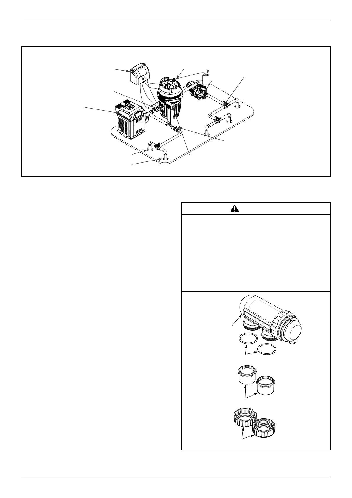
3. Put the lock nuts onto the inlet and outlet
pipes in the correct orientation, see Figure 4.
4. Glue the unions directly onto the pipes.
5. Ensure the o-rings are seated properly on the
unions.
6. Secure the cell to the plumbing by
tightening the unions hand tight. DO NOT
OVERTIGHTEN.
7. Double check cell orientation. The cell inlet is
closest to the cell electrical lead.
WARNING
a. The cell must be installed horizontally and level. Improper
installation can lead to gas build up which could result in
equipment damage or serious injury.
b. The cell must be the last piece of equipment on the return line.
c. It is recommended in all installations that the cell is installed on
a bypass equipped with isolation valves.
d. In order to avoid load loss, installing the cell on a bypass is
MANDATORY if system flow rated exceeds 300 Lpm.
e. If installing on a bypass, use a downstream check valve instead
of a manual valve to prevent improper back flow into the cell.
Cell
Unions
Lock Nuts
Adapter O-ring
Figure 4. Cell Plumbing Assembly