ASUS P5M2 Series
2-37
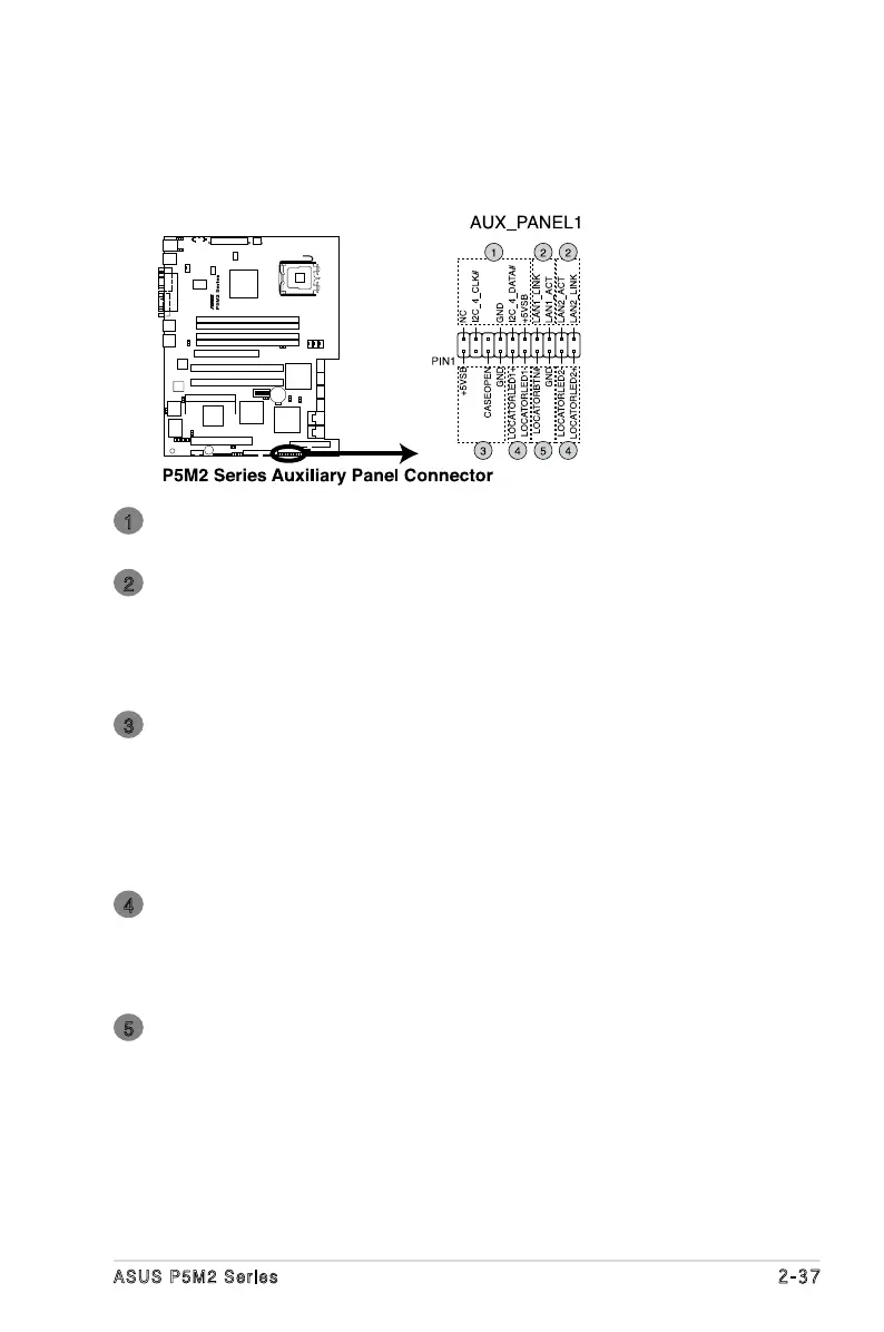
14. Au xil iar y p ane l c onn ect or (20 -pi n AUX_PA NEL 1)
This connector is for additional front panel features including front panel
SMB, locator LED and switch, chassis intrusion, and LAN LEDs.
Front Panel SMBus (6-1 pin)
These leads connect the front panel SMBus cable.
LAN link activity LED (2-pin LAN1_LINKACTLED and 2-pin LAN1_
LINKACTLED)
Both of the 2-pin connectors are for the LAN1 and LAN2 Activity LED.
Connect the LAN Activity LED cable to this connector.
This LED blinks during a network activity and is always lit when linked.
Chassis Intrusion connector (4-1pin CASEOPEN)
This lead is for a chassis with an intrusion detection feature. This
requires an external detection mechanism such as a chassis intrusion
sensor or microswitch. When you remove any chassis component, the
sensor triggers and sends a high-level signal to this lead to record a
chassis intrusion event. The defaults setting is to place one jumper cap
over the CASEOPEN and GND leads for disabled this feature.
Locator LED (2-pin LOCATORLED1 and 2-pin LOCATORLED2)
Both of the 2-pin connector is for the Locator LED 1 and LED 2. Connect
the Locator LED cable to this 2-pin connector.
This LED lights up when the Locator button is pressed.
Locator Button/Switch (2-pin LOCATORBTN)
This connector is for the locator button. This button queries the state of
the system locator.
1
2
3
4
5