12
DCB-05V2 Gate Controller Owner Installation Instructions
9. Safety Obstruction Force Test
WARNING! Take care when testing or adjusting the
Safety Obstruction Force. Excessive force may cause
SERIOUS PERSONAL INJURY and/or PROPERTY
DAMAGE.
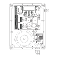
9.1 Testing Close Cycle (Single Swing Gates)
a. Press the OPEN button to open the gate.
b. Place a piece of timber approximately 40mm high on the ground
directly next to the closing pilon / fence (Fig. 9.1).
c. Press the CLOSE button to close the gate. The leaf of the gate
should strike the object and start to re-open.
9.2 Testing Open Cycle (Single Swing Gates)
a. Press the CLOSE button to close the gate.
b. Press the OPEN button to open the gate. When the gate reaches
the half open point, grab the side rail of the gate firmly and the
gate should stop.
c. If the gate does not reverse readily when closing, or stop when
opening, the force may be excessive and need adjusting.
WARNING! If the gate fails these tests, put the opener
into manual mode, only operate the gate by hand and
call for service.
Fig 9.1
40mm Block of wood
Safety Obstruction Force
The Safety Obstruction Force is calculated automatically during
setup. Adjusting this is normally only necessitated by environmental
conditions such as windy or dusty areas, and areas with extreme
temperature changes.
PREV NEXT
EXIT
SET
PRESS
M1: CLOSE Margin
(Amps) 0.7
PRESS
Fig 9.2
Fig 9.3
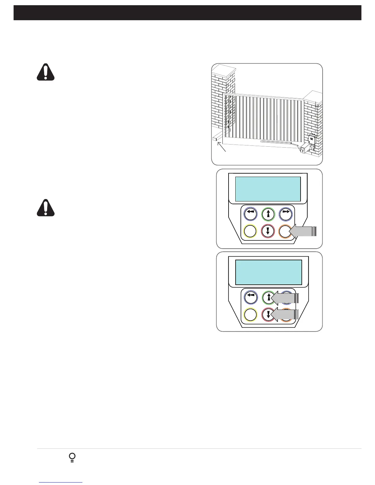
9.3 Force Pressure For Close Cycle.
Navigating To “Current Trips”
a. Press NEXT or PREV to navigate to Menu 2 Current Trips.
b. Press SET (Fig.9.2)
c. MENU 2.1: CLOSE Margin is displayed (Fig. 9.3).
d. Press UP arrow to increase or DOWN arrow to decrease
the value.
e. Press SET to save the new value.
NOTE: For dual gates repeat the same process for Motor 2
f. Test the force again as per “Safety Obstruction Force Test”
in Section 9.1.
9.4 Force Pressure For Open Cycle.
Navigating To “Current Trips”
a. Press NEXT to navigate to the Menu 2 Current Trips.
b. Press SET (Fig. 9.2)
c. Press NEXT.
d. MENU 2.2: OPEN Margin is displayed.
e. Press UP arrow to increase or DOWN arrow to decrease
the value.
f. Press SET to save the new value.
NOTE: For dual gates repeat the same process for Motor 2
g. Test the force again as per “Safety Obstruction Force Test”
in Section 9.2
9.5 Reprofiling Travel
a. Reprofiling is a simplified way of re-learning the travel
characteristic of a previously setup Limit Switch travel
installation. Re-profiling can be used when the travel
characteristics of the gate(s) change due to mechanical
adjustments etc. To initiate a re-profile, simply locate
“MENU 10.3 Reprofile Travel”, press SET and follow
the prompts. The gate(s) will start to move and
re-calculate force margins. The gate(s) can move between
the open and close limit positions up to two (2) times
(depending on the position of the gate(s) and the power up
condition).
b. A single beep will be heard once the process is complete.
c. Test the force again as per “Safety Obstruction Force Test”
(Section 9.1 and 9.2).