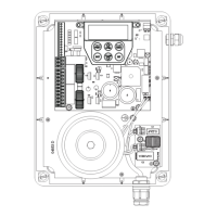
Owner Installation Instructions DCB-05V2 Gate Controller 5
MOTOR 1 terminal 2
V PWR for accessories
0V
Standby battery /
solar charger connector
24VAC power input
(from transformer)
10 amp fuse
Programmer / Network Input
Console keypad
Console display (LCD)
Antenna connector
3. Set Up Requirements
Fig 3.1
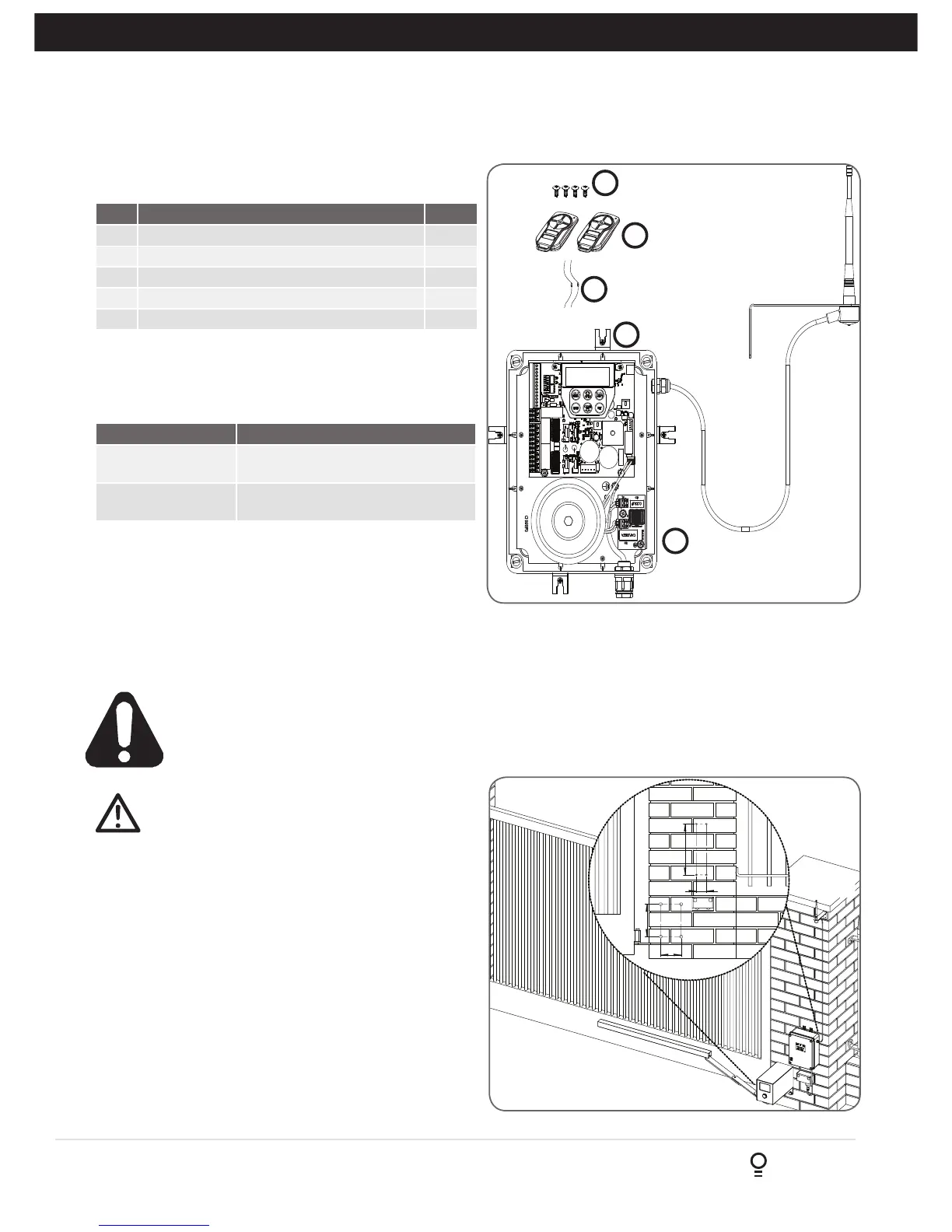
3.1 Kit Contents
3.2 Choosing your Set up
The DCB-05V2 can be set up in various ways and therefore
may require additional items. Common Set ups are as follows;
Item Description Qty
1 GATE CONTROL SYSTEM DCB05 1
2 MOUNTING LUGS FOR GEWISS BOX 4
3 SCREW “P” M3.5 X 13 4
4 TRIO-CODE 4B PTX-5V2 TRANSMITTER 2
5 RESISTOR 5K6 2
1
2
3
4
5
Set Up Items Required
Automated Set Up Drive Unit, control system and
transmitter
Automated Set Up
with Safety Beams
Drive Unit, control system, transmitter
and safety beams (optional extra)
4. Installation Requirements
IMPORTANT SAFETY INSTRUCTIONS FOR INSTALLATION
Warning: Incorrect installation can lead to severe injury.
Follow ALL installation instructions.
CAUTION: do not use any cables which carry
green/yellow wires as this signifies earth, and do
not comply with electrical authority regulations.
4.1 Mounting Control Box
a. The control box should be mounted near the drive unit
using four (4) 6mm screws.
b. Drill holes as per (Fig. 4.1). When locating the control
box, allow ample space around the unit for easy access
and wiring connections.
c. Remove cover from control box.
d. Dual Gates Only- Determine which leaf you would like to
open first and close last. This gate leaf must be connected
to Motor 1 (M1) terminals on the control board.
e. Connect drive unit(s) to control board. For detailed
electrical connection see Section 5.
4.2 Installing antenna
Mount the antenna at or above the height of the gate
or fence (whichever is higher) for optimal reception.
Do not cut the coaxial cable.