28
DCB-05V2 Gate Controller Owner Installation Instructions
Fig G.2
Menu Option
Operation
Code Operation (location
empty)
If the code operation is selected on an empty transmitter location, the BASIC CODE
TRANSMITTER PROCEDURE will be initiated with the transmitter being saved in the selected
location. This is useful when managing transmitters using a scheme which ties the store
location to the transmitter’s owner.
Code Operation (location used) If the code operation is selected for a location that already contains a transmitter, then the
BASIC CODE TRANSMITTER PROCEDURE will be initiated and the new transmitter will
replace the existing one. Note that the button functions and name of the existing transmitter
will be transferred to the new transmitter. This procedure is of great convenience when
replacing a lost transmitter.
Delete Operation The delete operation is used to remove a transmitter from memory along with the name and
button function settings.
Edit Operation The edit operation displays the transmitter record for editing purposes. See TRANSMITTER
EDIT PROCEDURE (Appendix F) for details.
Copy Operation The copy operation is used to code multiple transmitters with the same button function as that of
the selected transmitter. Once selected an abbreviated code set routine is initiated which repeats
steps 2 & 3 of the BASIC CODE TRANSMITTER PROCEDURE for each transmitter to be coded.
Coding is terminated by pressing the EXIT button.
Exiting The List
To exit the transmitter list, simply press EXIT to return to the Code menu.
PLEASE NOTE, THE FOLLOWING INSTALLATIONS ARE FOR 2
WIRE SETUPS ONLY
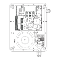
Selecting The Number Of Motors
a. Press NEXT to navigate to Menu 10.1.
b. The DCB-05V2 will now prompt for the number of motors
connected to be entered.
c. Use the UP or DOWN arrows to select the correct number and
then press SET (Fig. H.1).
d. Press EXIT.
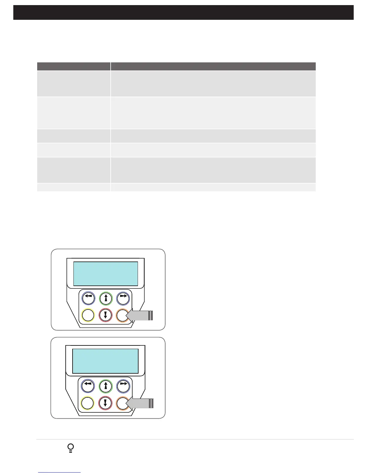
Navigating To “Limit/AMP Travel Menu”
a. Press NEXT to navigate to Menu 10.
b. Presee SET to locate Menu 10.1.
c. Press SET again to start the limit setting procedure .
d. DCB-05V2 will prompt you to confirm that the motor wiring
is complete (Fig. H.2) and that the gate(s) are at fully open
position and engaged.
e. Press SET to confirm.
f. DCB-05V2 will now automatically detect the type of drive unit
used by the number of wires used. If the correct number of wires
is displayed then press SET to continue otherwise press EXIT
and check the wiring.
g. DCB-05V2 will now automatically detect if one or two motor are
connected. If the correct number is displayed then press SET to
confirm. Otherwise press EXIT and check the wiring (Fig. H.3).
Fig H.1
Fig H.2
H- AMP Travel (2 Wires Setup)
Appendix