2
DCB-05V2 Gate Controller Owner Installation Instructions
Automatic Technology Australia Pty Ltd to the extent that such may be lawfully excluded hereby expressly disclaims all conditions or warranties, statutory
or otherwise which may be implied by laws as conditions or warranties of purchase of an Automatic Technology Australia Pty Ltd Garage Door Opener.
Automatic Technology Australia Pty Ltd hereby further expressly excludes all or any liability for any injury, damage, cost, expense or claim whatsoever
suffered by any person as a result whether directly or indirectly from failure to install the Automatic Technology Australia Pty Ltd Garage Door Opener in
accordance with these installation instructions.
Dual Gate Controller
24 Volt Gate Control System DCB-05V2
Contents
1. Important Safety Instructions 3
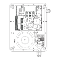
2. Control Board Layout 4
3. Set Up Requirements 5
3.1 Kit Contents 5
3.2 Choosing your Set up 5
4. Installation Requirements 5
4.1 Mounting Control Box 5
4.2 Installing antenna 5
5. Wiring Diagrams - Single Gates 6
5.1 Wiring motors and limit switches 6
5.2 Diodes 1N4004 or equivalent 6
6. Wiring Diagrams - Dual Gates 7
6.1 Wiring motors and limit switches 7
6.2 Diodes 1N4004 or equivalent 7
6.3 Dual NeoSlider Kit 8
7. Programming the DCB-05V2 9
7.1 Common Programs 9
7.2 Powering up the DCB-05V2 9
8. Setting Limits 10
8.1 Setting Travel Limits 10
8.2 Adjusting Close Limit(s) 10
8.3 Adjusting Open Limit(s) 10
8.4 Automatic Profiling 10
8.5 Code A Transmitter For Limit Setting 11
8.6 Setting Limits Via Transmitter 11
9. Safety Obstruction Force Test 12
9.1 Testing Close Cycle (Single Swing Gates) 12
9.2 Testing Open Cycle (Single Swing Gates) 12
9.3 Force Pressure For Close Cycle. 12
9.4 Force Pressure For Open Cycle. 12
9.5 Reprofiling Travel 12
10. Coding Transmitter 13
10.1 Coding Transmitter Button 13
10.2 Selecting Function Of The Button 13
10.3 Returning To Main Screen 13
11. Remotely Coding Transmitters 13
11.1 Selecting The Function To Be Coded 13
12. Setting Pedestrian Position 14
12.1 Setting the Pedestrian Position 14
12.2 Checking Pedestrian Position 14
12.3 Error Displays 14
11.2 Activate Remote Code Set Mode 14
13. Auto-Close Mode 15
13.1 Setting Up Standard Auto-Close 15
13.2 Safety Beam Triggered Auto Close 15
13.3 Pedestrian Auto-Close 15
13.4 Auto-Close After Obstruction: 15
14. Accessories Installation 16
14.1 Fitting Solenoid Or Magnetic Locks 16
14.2 Fitting Courtesy Lights 16
15. Battery Replacement 16
16. Battery Disposal 17
17. Specifications 17
18. Troubleshooting 18
19. Appendix 19
A - Console Menu Structure 19
B - Viewing and Editing Parameters 22
C - Control Board Adjustments 23
D- Diagnostic Tools 24
E - Memory Tools 26
F- Transmitter Editing 26
G- Transmitter Managment 27
H- AMP Travel (2 Wires Setup) 28
I - Time Travel 2 Wire Setup 30
20. Warranty and Exclusion of Liability 31