24
DCB-05V2 Gate Controller Owner Installation Instructions
C - Control Board Adjustments
Appendix
The controller provides several diagnostic tools from within the
Diagnostics Menu (Menu 8). This section details the function of
each tool and its use.
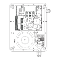
Navigating To Diagnostics Menu
a. Press PREV to navigate to Menu 8 (Fig. D.1).
b. Press SET to display the menu of available functions.
c. Press PREV or NEXT to cycle through diagnostic tools.
d. Press SET to select.
Menu 8.1 Test Inputs
This tool is used to view the state of the control inputs. When
selected, a screen is displayed (Fig. D.2) which indicates the
state of each input. If the name of the input is in upper case or
number in the bracket, then the input is active. Conversely if the
input is in lower case and [---] dash in the bracket, then the input
is inactive. For normal operation, all inputs should be inactive.
When finished, press EXIT. The example shows the status as OSC
input is active.
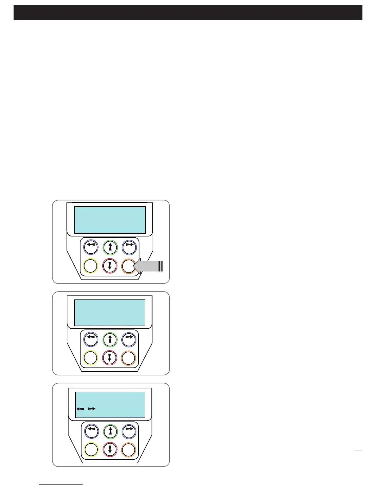
Menu 8.2 Test Transmitters (Tx’ers)
This tool is used to test receiver/transmitter functionality. When
selected, a screen is displayed which prompts for a transmitter
button to be pressed (Fig. D.3) and whether ID or serial numbers
are to be displayed.
DCB-05V2 will then beep each time a transmission is received. If
the transmitter button is stored in the DCB-05V2’s memory and
has a function assigned to it, a second screen will be displayed
that shows the transmitter details along with the button pressed
(Fig. D.4). The example shows the case where transmitter number
12 is activated by button 4. Note ID is selected for display.
Fig D.1
Fig D.2
Fig D.3
D- Diagnostic Tools
Appendix
Menu 7.15 Output2 Mode
AUX output can be selected to be driven by:
i. Lock Drive: Lock output can be programmed for both hold and pulse mode. The operation of the lock can
be programmed to activate prior to the gate and behave differently on open cycles to that on close cycle.
ii. Light Drive: a light relay module can be connected on the console between V+ and OUT2 terminal which will
turn the courtesy light on and off.
iii. 3 Wire Safety Beam 0V:
iv. Not Used
Menu 7.16 Fault, Auto Reset
When selected, the controller will reset any fault automatically.
Menu 7.17 Safety Beam Failure Emergency Close Mode (SBFEC)
When a safety beam prevents movement due to any reason other than a ‘real’ obstruction, the user can secure their
property by pressing and holding a button on the remote control or OSC on the console. The button must be held active
for more than five seconds to activate this mode and hold the button for the entire duration of close cycle.