6
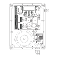
DCB-05V2 Gate Controller Owner Installation Instructions
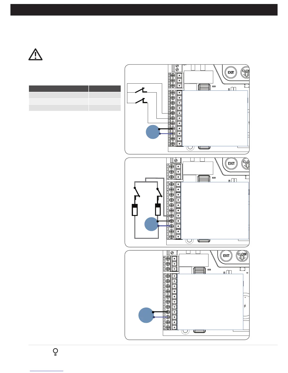
5. Wiring Diagrams - Single Gates
5.1 Wiring motors and limit switches
DCB-05V2 can be connected to the single gate
drive units in one of several ways.
Wiring Figure #
5 Wire, Single Gate 5.1
3 Wire Single Gate 5.2
2 Wire Single Gate 5.3
The diagrams (Fig. 5.1 to Fig. 5.3) show the
various wiring methods used for different drive
unit types. Select the appropriate method for your
drive unit.
NOTE:“non-motor current carrying limit-switch”
type drive units can be connected using the
standard 5 wire connections or a special 3 wire
method that uses a single limit switch sense wire
and two diodes.
5.2 Diodes 1N4004 or equivalent
(not included)
The most common function of a diode is to allow
an electric current to pass in one direction and
to block the current in the opposite direction.
The diode is a unidirectional electronic
component. It must be used as shown in
Fig. 5.2 to work properly.
NOTE: The motor travel direction can be
reversed by swapping the motor connections. An
opportunity to confirm the correct motor polarity
is provided during the limit setup procedure.
MI
Close
MOTOR 2 TERMINAL 1
MOTOR 2 TERMINAL 2
MOTOR 2 CLOSE LIMIT SWITCH INPUT
MOTOR 2 OPEN LIMIT SWITCH INPUT
COMMON FOR MOTOR 1 & 2 LIMIT SWITCHES
MOTOR 1 CLOSE LIMIT SWITCH INPUT
MOTOR 1 OPEN LIMIT SWITCH INPUT
MOTOR 1 TERMINAL 1
MOTOR 1 TERMINAL 2
V PWR FOR ACCESSORIES
OV
Open
MOTOR 1
MOTOR 2 TERMINAL 1
MOTOR 2 TERMINAL 2
MOTOR 2 CLOSE LIMIT SWITCH INPUT
MOTOR 2 OPEN LIMIT SWITCH INPUT
COMMON FOR MOTOR 1 & 2 LIMIT SWITCHES
MOTOR 1 CLOSE LIMIT SWITCH INPUT
MOTOR 1 OPEN LIMIT SWITCH INPUT
MOTOR 1 TERMINAL 1
MOTOR 1 TERMINAL 2
V PWR FOR ACCESSORIES
OV
MI
MOTOR 1
1N4004 diode
open
close
1N4004 diode
MOTOR 2 TERMINAL 1
MOTOR 2 TERMINAL 2
MOTOR 2 CLOSE LIMIT SWITCH INPUT
MOTOR 2 OPEN LIMIT SWITCH INPUT
COMMON FOR MOTOR 1 & 2 LIMIT SWITCHES
MOTOR 1 CLOSE LIMIT SWITCH INPUT
MOTOR 1 OPEN LIMIT SWITCH INPUT
MOTOR 1 TERMINAL 1
MOTOR 1 TERMINAL 2
V PWR FOR ACCESSORIES
OV
MI
MOTOR 1