Limits Motor
C O
Com
1
2
MSI-1.00 Board
Limits Motor
C O
Com
1
2
MSI-1.00 Board
ATA DCB-05V3 (150VA)
MOTOR 2 TERMINAL 1
MOTOR 2 TERMINAL 2
MOTOR 2 CLOSE LIMIT SWITCH INPUT
MOTOR 2 OPEN LIMIT SWITCH INPUT
COMMON FOR MOTOR 1 & 2 LIMIT SWITCHES
MOTOR 1 CLOSE LIMIT SWITCH INPUT
MOTOR 1 OPEN LIMIT SWITCH INPUT
MOTOR 1 TERMINAL 1
MOTOR 1 TERMINAL 2
V PWR FOR ACCESSORIES
OV
Red
Black
White
Blue
Orange
Black
White
Orange
Red
Blue
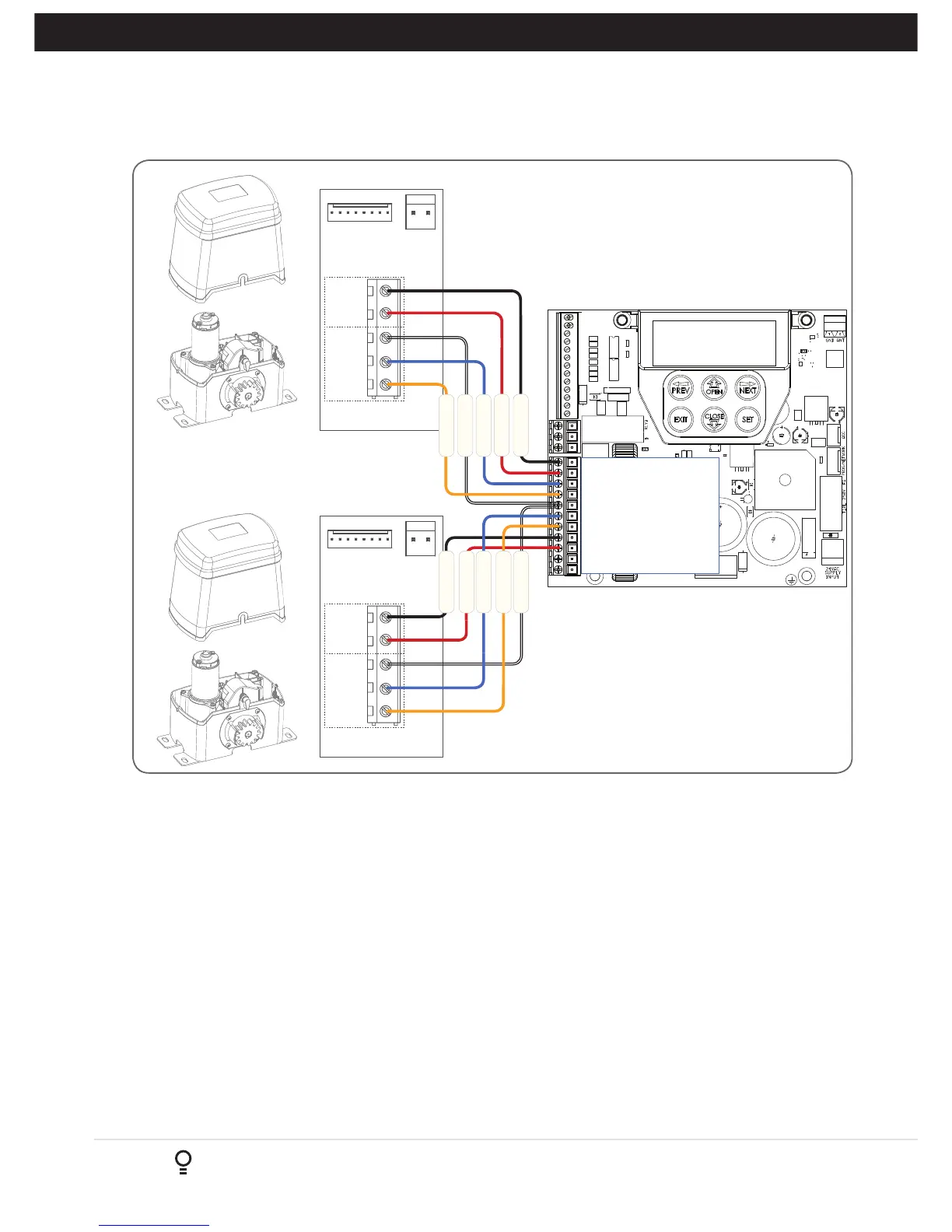
Fig 6.4
6.3 Dual NeoSlider Kit
This section illustrates how to wire two NeoSlider
TM
slave openers into a DCB-05V2. (Fig. 6.4)
NOTE:
When setting limits, if both openers are travelling in different directions (i.e one is opening and the other is
closing), then do the following:
a. Switch over the motor wires (marked red and black in Fig 6.4) on the incorrectly behaving openers MSI board.
b. Restart the limit set up process.
6.
Wiring Diagrams - Dual NeoSlider Kit