4
DCB-05V2 Gate Controller Owner Installation Instructions
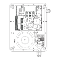
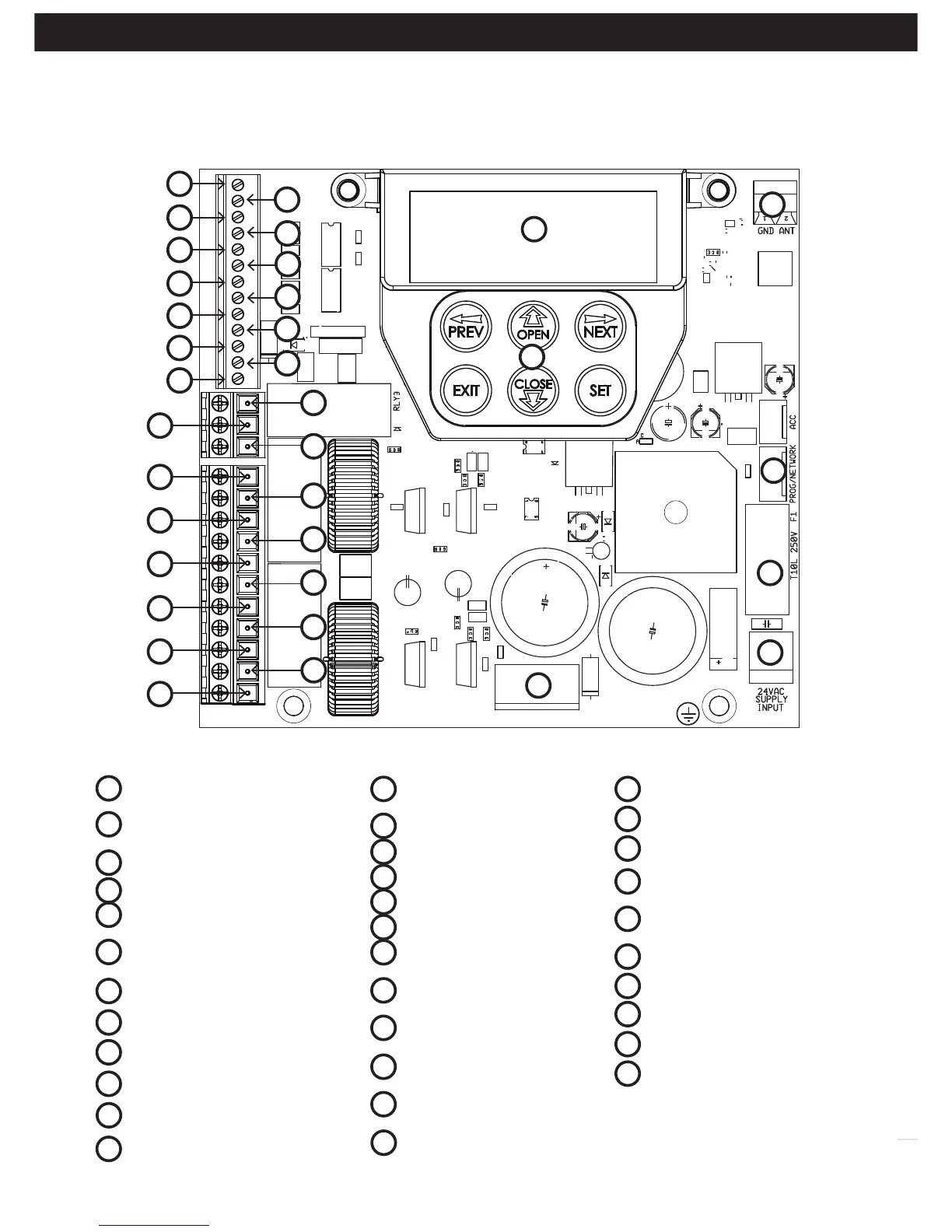
2. Control Board Layout
SB2 (Safety Beam (2),
two, three wire or wireless)
SB1 (Safety Beam(1),
two, three wire or wireless)
0V
Aux control input
OPN Programmable
N/O or N/C input terminal
STP Programmable
N/O or N/C input terminal
CLS N/O input terminal
OSC N/O input terminal
SWP N/O input terminal
PED N/O input terminal
0V
V+
28
29
13
34
33
30
31
01
02
03
04
05
06
07
08
09
10
11
12
Fig 2.1
32
OUT 2 (optional relay
module coil drive)
OUT 1 N/C relay contact
OUT 1 COM relay contact
OUT 1 N/O relay contact
MOTOR 2 terminal 1
MOTOR 2 terminal 2
MOTOR 2 close limit switch
input terminal
MOTOR 2 open limit switch
input terminal
COM terminal for Terminals
19,20,22 &23.
MOTOR 1 close limit switch
input terminal
MOTOR 1 open limit switch
input terminal
MOTOR 1 terminal 1
13
MOTOR 1 terminal 2
V PWR for accessories
0V
Standby battery /
solar charger connector
24VAC power input
(from transformer)
10 amp fuse
Programmer / Network Input
Console keypad
Console display (LCD)
Antenna connector
14
15
16
17
18
19
20
21
22
23
24
25
26
27
28
29
30
31
32
33
34
01
02
03
04
05
06
07
08
09
10
11
12
27
15
17
19
21
23
25
14
16
18
20
22
24
26