16
DCB-05V2 Gate Controller Owner Installation Instructions
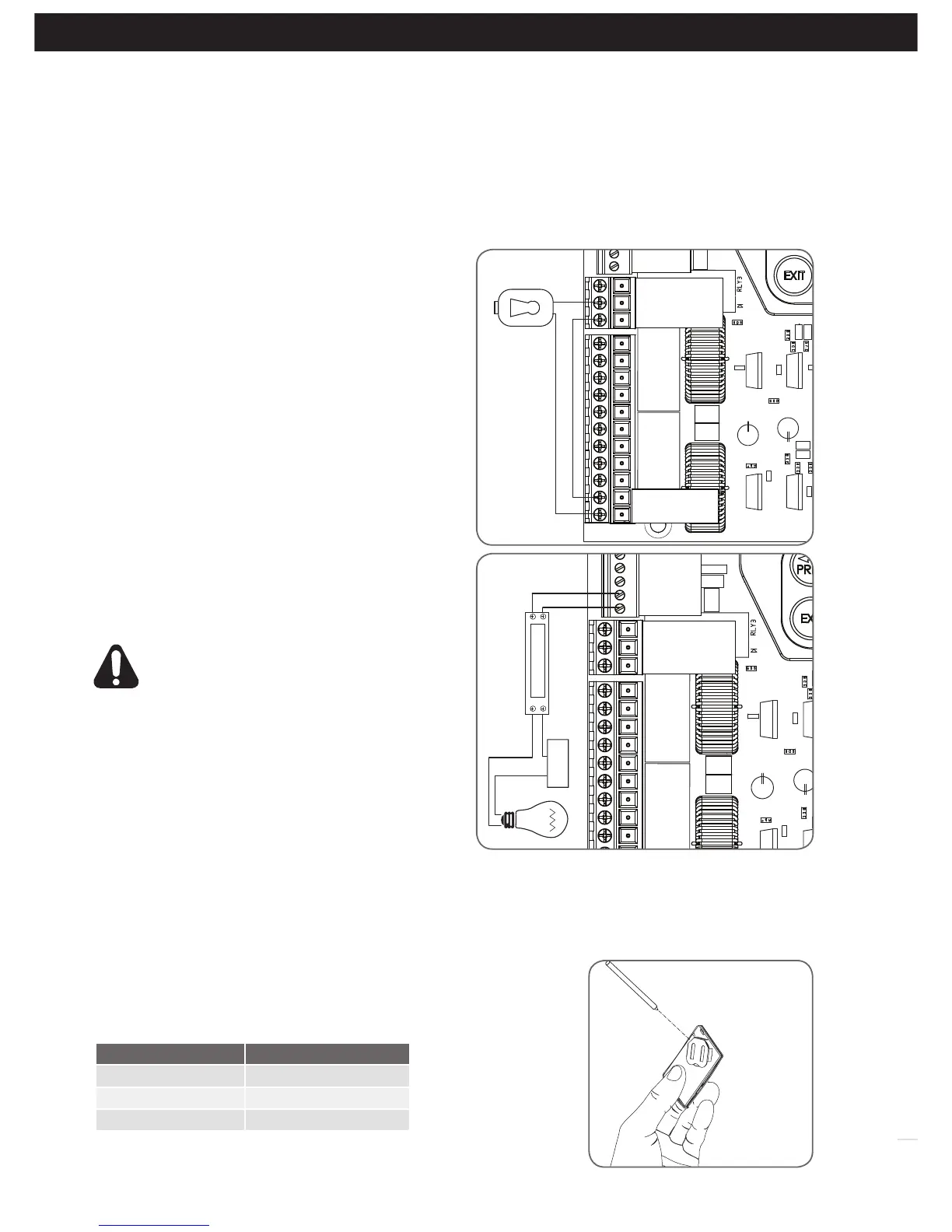
14.2 Fitting Courtesy Lights
An AC or DC courtesy light can be activated via an output
on the gate opener control board. Connect the light as per
the diagram. (Fig. 14.2)
WARNING: A qualified electrician must perform
the installation where 240V AC power is used.
Menu 5. Light Times
a. Press NEXT or PREV on the wall control unit to navigate
to Menu 5 Light/Lock Times.
b. Press SET to select the sub menu.
c. Press NEXT or PREV to navigate through the sub menu.
d. Press OPEN to increase or CLOSE to decrease the time.
e. Press SET to save the new time.
f. Press the EXIT button two times to exit.
g. Test the light operation.
14. Accessories Installation
SAFETY B2
SAFETY B1
OV
AUX
OPEN
STOP
CLOSE
OSC
SWIPE
PEDESTRIAN
OV
V+
OUT2
OUT1 N/C
OUT1 COMMON
OUT1 N/O
LIGHT RELAY MODULE
POWER
SUPPLY
Wiring Output1 And Output2
Outputs 1 and 2 are used to control a lock and a light. Which output is to control which function and the way it is controlled
is programmable. If using these outputs make sure that the functions are configured for correct operation prior to setting
the travel limits. OUTPUT1 is a relay output with high current capability. OUTPUT2 is used to activate an optional external
relay module (RO-1) which in turn is used to switch the load.
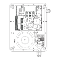
14.1 Fitting Solenoid Or Magnetic Locks
Install the lock mechanism on the gate as per the manufacturers
instructions. See Fig. 14.1 for the wiring diagram.
Menu 4. Lock Times
Lock output can be programmed for both hold and pulse
mode. The operation of the lock can be programmed to
activate prior to the gate and behave differently on open
cycles to that on close cycles.
a. Press NEXT or PREV on the wall control unit to navigate to
Menu 4 Lock Times.
b. Press SET to select the sub menu.
c. Press NEXT or PREV to navigate through the sub menu.
d. Press OPEN to increase or CLOSE to decrease the time.
e. Press SET to save the new time.
f. Press the EXIT button two times to exit and test the locks
operation.
SAFETY B2
SAFETY B1
OV
AUX
OPEN
STOP
CLOSE
OSC
SWIPE
PEDESTRIAN
OV
V+
OUT2
OUT1 N/C
OUT1 COMMON
OUT1 N/O
Pulse Lock
V PWR
OV
Fig 14.1
Fig 14.2
15.1 Removing the Battery From the Transmitter
(Battery Type: 3V Lithium Battery CR2032).
Use a non-metallic object (e.g. pen) to remove the battery. (Fig. 15.1). To
test the battery is working, press and hold a transmitter button; (Fig. 15.2).
Light Status Battery Status
Solid OK
Flashing Requires replacement
No light Requires replacement
REPLACE
BATTERY WITH
CR2032 ONLY
Fig 15.1
Fig 15.2
Use a pen
to push the
battery down
through the
side opening
to release
battery
15. Battery Replacement