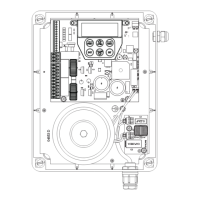
Owner Installation Instructions DCB-05V2 Gate Controller 9
7. Programming the DCB-05V2
7.1 Common Programs
The two most common programs are;
Program Menu’s required Function Section
Automated Set Up Menu 10.1 Setting the Limits 8.1
Safety Obstruction Force 9.1 and 9.2
Menu 1 Coding the Transmitter 10.1
Automated Set Up with
Safety Beams
Menu 10.1 Setting the Limits 8.1
Safety Obstruction Force 9.1 and 9.2
Menu 1 Coding the Transmitter 10.1
Menu 3 Auto Close Times 13.2, 13.3 and 13.4
NOTE: Fitting Safety Beams enables the Auto-Close feature to become active.
CAUTION: Before plugging the gate control system
in, check the power cord for damage and ensure it
cannot become entangled in any moving parts
7.2 Powering up the DCB-05V2
a. After checking the initial wiring, apply power to the DCB-05V2.
The controller will go through a startup sequence displaying
the STARTUP SCREEN which indicates the controller type
and firmware version (Fig. 7.2). After a short delay the MAIN
SCREEN will be displayed.
b. If this is the first time the DCB-05V2 has been used, the MAIN
SCREEN should indicate that the limits are not set (Fig. 7.3).
If the display shows that some input is active then rectify
the situation before proceeding. If a default setting is to be
changed it should be done now before setting the travel limits.
A.T.A GCS24
FIRMWARE X.XX
PREV NEXT
EXIT
SET
Limits Not Set!
Press <> To Acess MENU
PREV NEXT
EXIT
SET
Start up screen
Main screen
Fig 7.2
Fig 7.3
Fig 7.1

 Loading...