Owner Installation Instructions DCB-05V2 Gate Controller 25
PREV NEXT
EXIT
SET
EVENT# 64
Close Complete
PREV NEXT
EXIT
SET
OSC PED LGT>VAC
124 ID B B SMITH
PRESS
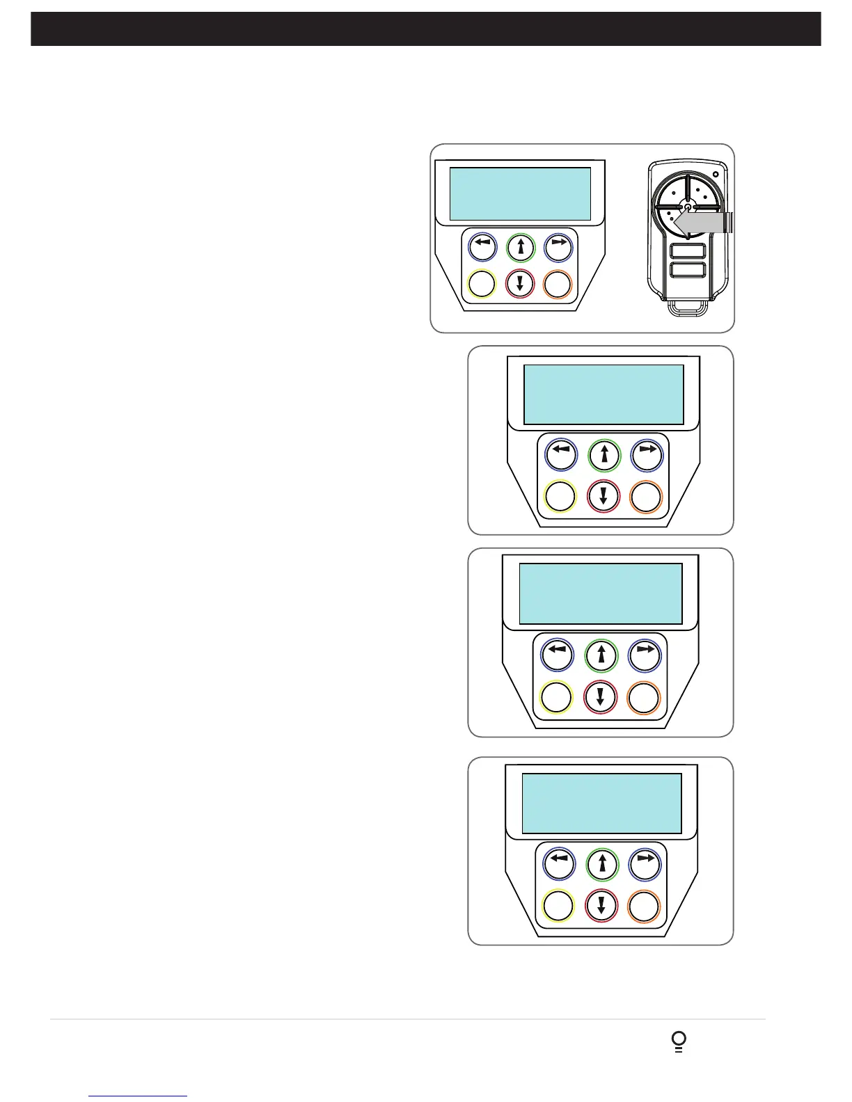
Fig D.4
Fig D.5
Menu 8.3 Display History
DCB-05V2 keeps a record of the last 64 events that
have taken place. The events include the type of
drive cycles executed, obstruction detection, various
faults, power failures etc. When this tool is selected,
the screen displays the last event that occurred
(Fig. D.5). Press NEXT or PREV to view each event. The
“EVENT#” field shows the sequence of the events, with (1)
being the first and (64) being the last. The example shows
that the last event was a close cycle which succeeded in
closing the gate. When finished viewing the events, press
EXIT.
Fig D.7
Fig D.8
D- Diagnostic Tools
Appendix
Menu 8.4 Memory Usage
This tool displays the number of transmitter store locations used
and the number free.
Menu 8.5 Service Counter
DCB-05V2 provides a periodic service counter which can be
set to expire after a number of drive cycles. When expired,
DCB-05V2 will beep at the beginning of each drive cycle
and a message will be displayed on the MAIN SCREEN
(Fig. D.7). This tool displays the current value of the service
counter and allows the user to set its value using the normal
parameter editing techniques (See PARAMETER VIEWING AND
EDITING). If the service counter is not to be used, it can be set
to the maximum number (60,000).
Menu 8.6 Event Counters
The opener keeps a count of number of times a particular event
occurs. The list of event counters kept is shown below. When this
tool is selected, the first event counter is shown (Fig. D.8). Press
NEXT or PREV to step through the list. The example shows the
OPEN CYCLE event counter with a value of 1234. When finished
viewing press EXIT.
1: Open Cycles 2: Close Cycles
3: PED Cycles 4: Warranty Cycles
5: Setup Limits 6: Overlaps
7: M1 Open Obstuctions 8 M2 Open Obstuctions
9: M1 Close Obstuctions 10: M2 Close Obstuctions
11: M1 Open Overloads 12: M2 Open Overloads
13: M1 Close Overloads 14: M2 Close Overloads
15: M1 Volts Faults 16: M2 Volts Faults
17: M1 AMP Faults 18: M2 AMP Faults
19: Supply High Faults 20: Supply Low Faults
21: M1 AMP Trip 22: M2 AMP Trip
23: 3W Limit Faults