QSG_F28+.394.00_EN_01 / 2019-02-25
18 / 42
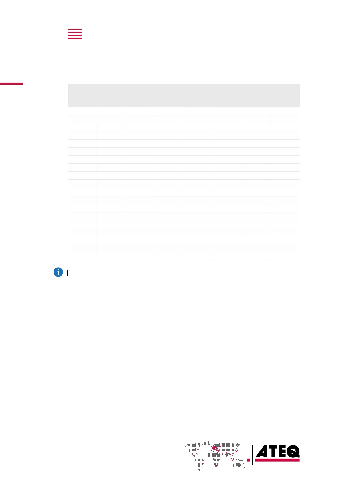
Program selection (J8 and J9)
The connectors J8 and J9 enable you to select a program from digital inputs.
Combinations of connector pins to activate for program selection
Program
number
J8 J9
Pin 5
(input 3)
Pin 6
(input 4)
Pin 7
(input 5)
Pin 8
(input 6)
Pin 9
(input 7)
Pin 1
(input 8)
Pin 2
(input 9)
1 0 0 0 0 0 0 0
2 1 0 0 0 0 0 0
3 0 1 0 0 0 0 0
4 1 1 0 0 0 0 0
5 0 0 1 0 0 0 0
6 1 0 1 0 0 0 0
7 0 1 1 0 0 0 0
8 1 1 1 0 0 0 0
9 0 0 0 1 0 0 0
10 1 0 0 1 0 0 0
11 0 1 0 1 0 0 0
12 1 1 0 1 0 0 0
13 0 0 1 1 0 0 0
14 1 0 1 1 0 0 0
15 0 1 1 1 0 0 0
16 1 1 1 1 0 0 0
17 to 32 X* X X X 1 X X
33 to 64 X X X X X 1 X
65 to 128 X X X X X X 1
* X is equal to 0 or 1 in function of the program number.
Valve code board connector (J10) (option)
Characteristics
— Outputs:
• 24 V DC - 100 mA max per output.
— Inputs:
• Activation: + 24 V DC.