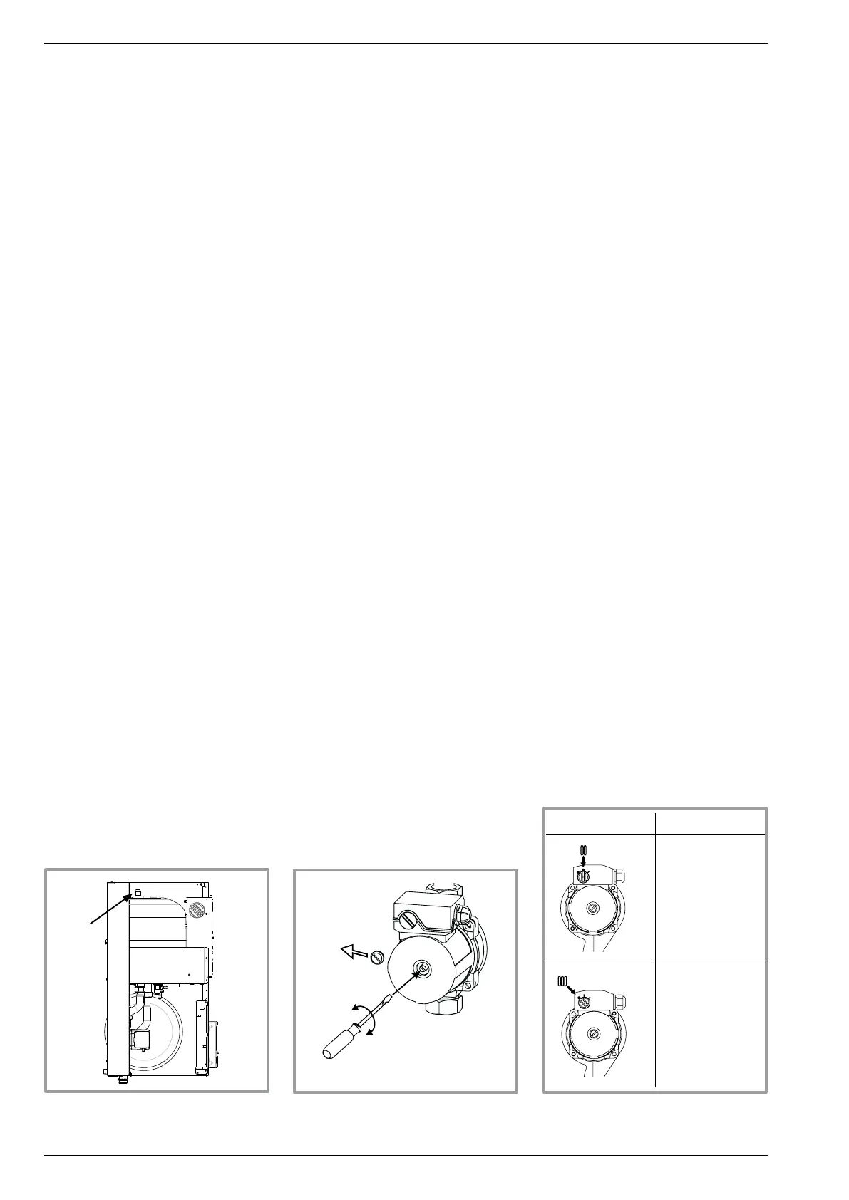
Speed N° 1
Not recommended
Speed N° 2
- Radiator
Speed N° 3
- Radiator
- Floor heating
system
- Fan convector
2.8 Connecting the heating
circuit hydraulically
2.8.1 General
The connection must comply with good trade practice
according to local building regulations.
The heating circulating pump is built into the
hydraulic unit.
Connect the central heating pipes to the appliance,
complying with the direction of circulation.
The pipe between the heat pump and the heat collector
must be at least one inch in diameter (26x34 mm).
Calculate the diameter of the pipes according to the
ow rates and the lengths of the hydraulic systems.
Tightening torque : 15 to 35 Nm.
Use union connectors to facilitate removing the
hydraulic unit.
Preferentially use connection hoses to avoid transmitting
noise and vibrations to the building.
Connect the drains from the drain valve and the safety
valve to the main sewer system.
Reminder: Seal everything when tting in accordance
with prevailing trade practice for plumbing work:
- Use suitable seals (bre seals, o-rings).
- Use Teon tape or hemp.
- Use sealing paste (synthetic depending on the case).
The use of glycol is not necessary.
If you are using a glycol/water mix, provide for an annual
check on the quantity of glycol. Use monopropylene
glycol only. Never use monoethylene glycol.
In certain installations, the presence of different metals
can cause corrosion problems; the formation of metal
particles and sludge in the hydraulic circuit is then seen.
In this case, it is advisable to use a corrosion inhibitor in
the proportions indicated by its manufacturer.
It is also necessary to ensure that the treated water
does not become aggressive.
2.8.2 Rinsing out the installation
Before connecting the hydraulic unit to the installation,
rinse out the heating system correctly to eliminate
any particles that may affect the appliance's correct
operation.
Do not use solvents or aromatic hydrocarbons (petrol,
parafn, etc.).
In the case of an old installation, provide a sufciently
large decanting pot with a drain on the return from the
boiler and at the lowest point in the system in order to
collect and remove the impurities.
Add an alkaline product to the water and a dispersant.
Rinse the installation several times before lling it
denitively.
2.8.3 Filling and purging the installation
Check the pipe xings, the tightness of the connectors
and the stability of the appliance.
Check the direction in which the water is circulating and
that all the valves open.
Proceed to ll the installation.
Do not operate the circulating pump while lling. Open
all the drain valves in the installation and the bleeder
valve for the hydraulic unit to remove the air contained
in the conduits.
Close the drain and bleeder valves and add water until
the pressure in the hydraulic circuit reaches 1,5 bars.
Check that the hydraulic circuit has been purged
correctly.
Check that there are no leaks and that the circulating
pumps are not seized (if need be, release them).
After the "Start-up" stage (see page 28), once the
machine has started, purge the hydraulic unit again.
2.8.4 Connecting a fan-convectors circuit
It must be installed on this circuit a buffer tank
(minimum capacity: 50 liters).
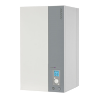
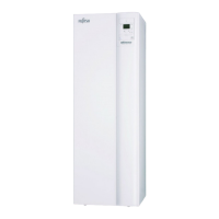
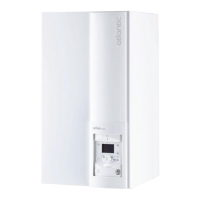
gure 21 - hydraulic unit
bleeder valve
P
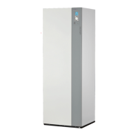
gure 22 - Release
of the circulation pump
gure 23 - Recommended
circulation speed
Installation and operation manual "1397 - EN"
Heat pump split single service alféa Evolution
- 20 -