QX1
N
EX1
EX2
EX3
X60
X86 X84
X11
X12
2
1
3
M B9
B2 M B1 3 2 1
1
2
1
3 2
B2M
B1
2.10 Outdoor sensor
The outdoor sensor is required for the heat pump to
operate correctly.
Consult the tting instructions on the packaging.
Place the sensor on the coldest part, generally the
northern or north-eastern side.
In any case, it must not be exposed to the morning sun.
It must be installed so as to be easily accessible but at
least 2,5m from the oor.
It is essential that it avoid any sources of heat such as
ues, the upper parts of doors and windows, proximity
to extraction vents, the underneath of balconies and
under-eave areas which would isolate the sensor from
variations in the outdoor air temperature.
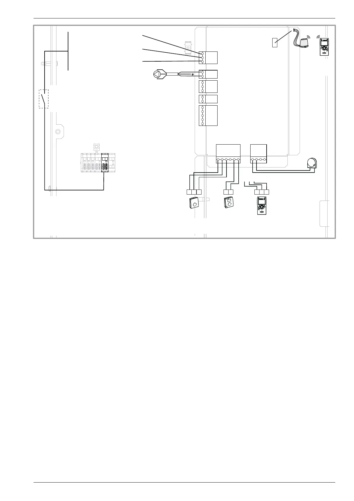
- Connect the outdoor sensor to the M and B9 terminals
on the heat pump control board.
2.11 Room thermostat
and/or room control unit (option)
The room thermostat (room control unit) is optional.
Consult the tting instructions on the packaging.
The sensor must be installed in the living room area on
a very uncluttered wall, 1,5 m above the oor.
Avoid direct sources of heat (chimney/ue, television,
cooking hobs), draughty areas (ventilation, door, etc.).
Air leaks in the seals in the constructions are often
translated into cold air blowing through the electrical
conduits. Lag the electrical conduits if there is a cold
draught on the back of the room thermostat.
• Installation tted with a room thermostat
- Connect the sensor to the X86 connector of the heat
pump’s regulator board using the connector provided
(terminals M, B2, B1 for the room thermostat T37 or
bor terminals nes 1, 2 for the room thermostat T55).
• Installation tted with a room control unit
- T75 : Connect the room control unit to
terminals 1, 2, 3 of the connector X86 on the heat
pump’s regulator board.
- T78 : Connect the wireless room panel to the
connector X60.
gure 31 - Connections to the heat pump regulator (accessories and options)
Outdoor
sensor
Heating circulation
pump
Room
thermostat
T55**
Room
thermostat
T37**
Room
control unit
T75**
Room
control unit
radioT78**
Power shedding or EJP
(peak day removal)
Tariffs, peak times/off-peak
times, day / night
External fault
External
component
contact* (faults, load
shedder, power meter)
* If the control device does not provide a potential-free contact,
the contact must be relayed to create equivalent wiring.
In all cases, please refer to the instruction manuals for the external
components (load shedder, power meters) to create the wiring.
** Option
T75 : The connection of terminal 3 of the room control unit T75 is
not mandatory (lighting of the room control unit.
oror
Installation and operation manual "1397 - EN" - 27 -
Heat pump split single service alféa Evolution