2.9.3 Overview of all the electrical connections
The wiring diagram for the hydraulic unit is shown in detail on gure 43, page 46.
2.9.4 Cable section and protection rating
The cable sections are given for information purposes only and do not exempt the installer from checking that these
sections correspond to the requirements and comply with the prevailing standards.
• Power supply to outdoor unit
Heat pump Electricity supply 230 V - 50 Hz
Model Maxi. power absorbed
Cable connection
(Phase, Neutral, Earth)
Curve D circuit
breaker size
Evolution 5, Evolution 6 3450 W 3 x 1,5 mm² 16 A
Evolution 8 3450 W 3 x 2,5 mm² 16 A
Evolution 10 3910 W 3 x 2,5 mm² 20 A
Evolution 13 4600 W 3 x 4 mm² 25 A
Evolution 16 5980 W 3 x 6 mm² 32 A
• Interconnection between the outdoor unit and the hydraulic unit
The hydraulic unit is powered by the outdoor unit by means of a cable with 4 wires 1,5 mm² (Phase, Neutral,
Earth, Communication bus).
• Power supply to the electrical back-ups (option)
The hydraulic unit contains two stages of electrical back-ups installed in a heat exchange tank.
Heat pump electrical back-ups Electrical back-ups supply
Model Power Nominal current
Cable
(Phase, Neutral, Earth)
Curve C circuit
breaker size
Evolution 5, 6, 8,
10, 13, 16
2 x 3 kW 26,1 A 3 x 6 mm² 32 A
bar
4
3
2
1
0
OK
ESC
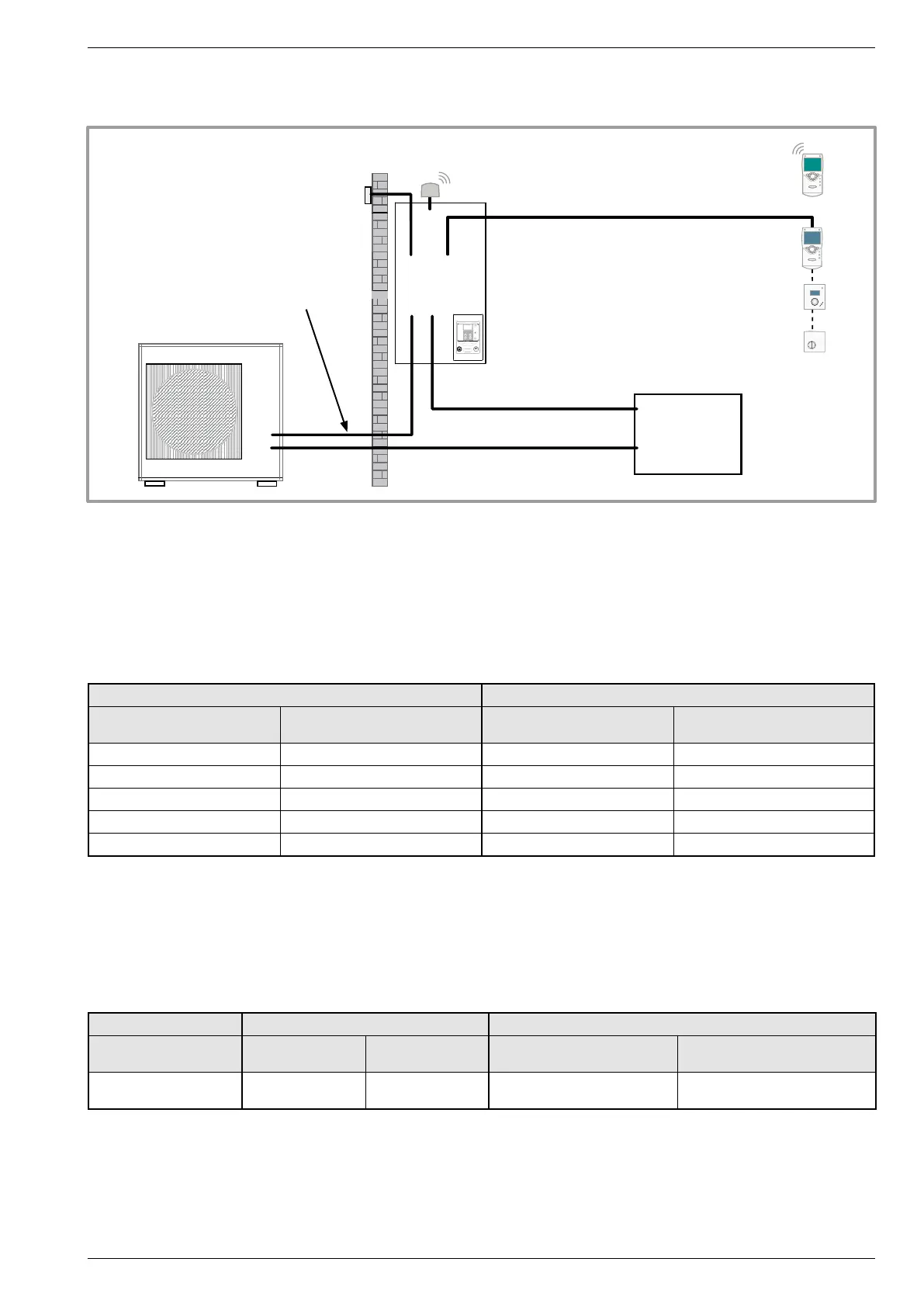
gure 24 - Overall layout of the electrical connections for a simple installation (1 heating circuit)
Outdoor sensor
cable 2 x 0.75mm²
Room thermostat T55 (option)
cable 2 x 0,5 mm²
Room thermostat T37 (option)
cable 3 x 0,5 mm²
Electric panel
Power supply to the electrical back-ups (option)
Phase, Neutral, Earth
cable 3 x 6 mm²
General electrical supply
Phase, Neutral, Earth
(see table below)
Interconnection between the outdoor unit
and the hydraulic unit:
Phase, Neutral, Earth, Communication bus
cable 4G 1.5mm²
Room control unit radio T78 (option)
Room control unit T75 (option)
cable 3 x 0,5 mm²
ou
ou
ou
Installation and operation manual "1397 - EN" - 23 -
Heat pump split single service alféa Evolution