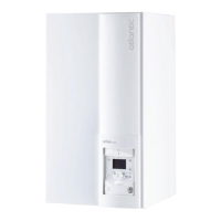
2.9.6 Electrical connections
on the hydraulic unit side
Access to the connection terminals:
- Remove the front panel (2 screws) ( gure 16, page 16).
- Open the power control box.
- Make the connections in accordance with the
diagram(s) ( gure 32).
Do not place the sensor lines and the sector supply
lines in parallel in order to avoid interferences due to
voltage points in the sector supply.
Ensure that all the electrical cables are housed in the
spaces provided for this purpose.
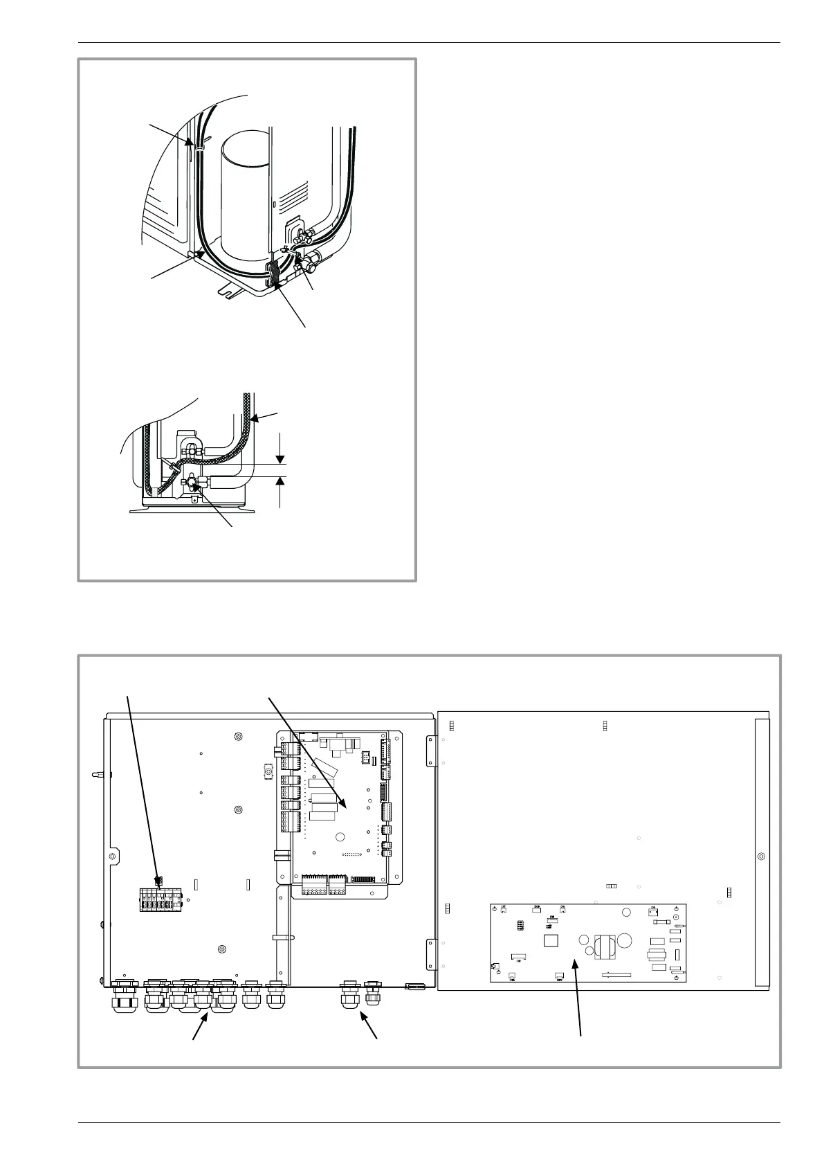
Dégagement
Serre-câble
Serre-câble
Plaque isolante
Câbles
(alimentation et
interconnexion)
Câbles
Vanne “gaz”
gure 28 - Finalisation of connection to outdoor unit
gure 29 - Access to hydraulic unit electric box and description
P
HP regulator
Cable grommet (power)
Terminal blocks
Interface card
Cable grommet (sensors)
Cable clamp
Flexible insulation
plate
Cables (supply and
interconnection)
Cables
Release
Gas valve
Cable clamp
Installation and operation manual "1397 - EN" - 25 -
Heat pump split single service alféa Evolution