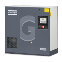
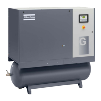
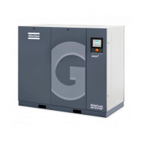
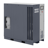
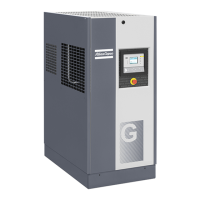
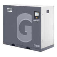
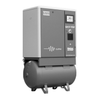
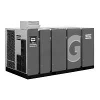
Flow diagram of air dryer on GA Full-Feature compressors
Air flow
Air drawn through filters (AF) and unloaders (UA) is compressed in compressor elements (E). Compressed
air and oil are discharged through check valves (CV) to air receiver/oil separators (AR) where oil is separated
from the compressed air. The air is blown through minimum pressure valves (Vp) to air coolers (Ca).
On GA Pack compressors, the cooled air is discharged through condensate traps (MTa) and outlet (AO)
towards the air net.
On GA Full-Feature compressors, the cooled air is discharged through condensate trap (MTa) and outlet (AO)
towards the air net via the integrated air dryer.
Check valves (CV) prevent blow-back of compressed air.
Minimum pressure valve (Vp) prevents the receiver pressure from dropping below a minimum pressure. The
valve has a built-in check valve.
Instruction book
16 2920 1475 06
 Loading...

