EasyManua.ls Logo

Atlas Copco MT Focus 400 - User Manual

Atlas Copco MT Focus 400
28 pages
Print Icon
To Next Page IconTo Next Page
Loading...
MT Focus 400
Printed Matter No. 9836 6294 01 Control and drive unit
Publication Date 2020-04-16
Valid from Serial No. A5690001
Valid to Serial No. A2509999
Product Instructions
MT FOCUS 400A 8432085000
WARNING
Read all safety warnings and instructions
Failure to follow the safety warnings and instructions may result in
electric shock, fire and/or serious injury.
Save all warnings and instructions for future reference
Question and Answer IconNeed help?

Do you have a question about the Atlas Copco MT Focus 400 and is the answer not in the manual?

Summary

Product Information

General Information

Safety warnings and general instructions for safe operation.

Safety Signal Words

Definitions of Danger, Warning, Caution, and Notice signal words.

Warranty

Details on product warranty terms and conditions.

Website

Information on where to find product details and resources online.

ServAid Portal

Online portal for technical information, safety, and spare parts.

Safety Data Sheets

Information on chemical products and safety data sheets.

Country of Origin

Information regarding the product's country of origin.

Dimensional Drawings

Location of dimensional drawings for the product.

Product Overview

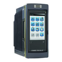
General introduction to the product and its applications.

Main Parts and Functions

Description of the controller's buttons and display.

Technical Data

Specifications including ordering number, voltage, power, and weight.

Technical Product Data

Where to find detailed technical product data.

Accessories

Lists of included and optional accessories for the MT Focus 400.

Service Overview

General overview of service and maintenance recommendations.

Service Recommendations

Guidelines for preventive maintenance and handling issues.

Installation

Installation Instructions

General instructions for installing the controller.

Basic Setup

Initial setup procedures for the controller.

Controller Connectors

Description of the controller's various connectors and their functions.

Connecting Accessories

Instructions and diagrams for connecting accessories.

Serial Interface (RS232-C)

Details on the RS232-C serial interface and its settings.

Vacuum Pump Output (VP)

Details on the 5-pole socket connector for the vacuum pump.

Configurable Single Input (I;O)

Information on the 5-pole pin connector for configurable inputs.

Input Resistance

Technical specification for input resistance.

Configurable Digital I;O

Details on the 15-pole D-sub connector for configurable signals.

PNP Mode

Explanation of PNP mode for digital I/O signals.

NPN Mode

Explanation of NPN mode for digital I/O signals.

Mechanical Installation

Methods for mounting the controller on a surface.

Wall Bracket Attachment

Steps for attaching the controller using a wall bracket.

Rear Screw Attachment

Instructions for mounting the controller with screws from the rear.

Operation

Ergonomic Guidelines

Advice for improving posture, placement, and work environment.

Configuration Reference

Reference to the ToolsTalk MT user guide for configuration.

Operating Instructions

Instructions for starting and operating the controller.

Controller Basics

Information on PSet storage and management.

Buttons and Indicator

Explanation of controller buttons and status indicator lights.

Auto-Set Procedure

Procedure for setting tightening parameters automatically.

Select Program Set (PSet)

Steps to select a program set for the controller.

Batch Control

Instructions for managing batch size, increment, decrement, and reset.

Auto-Start Function

How to activate and manage the auto-start function.

Deactivate Auto-Start

Steps to disable the auto-start function.

Temporarily Disable Auto-Start

Method to temporarily disable auto-start using an object.

Service

Preventing ESD Problems

Precautions against electrostatic discharge during service.

Maintenance Instructions

General guidelines for maintaining the system's efficiency.

General Maintenance

General maintenance procedures, service reminders, and environmental factors.

Controller Servicing

Required tools and procedures for opening the controller.

Opening the Cover

Step-by-step guide to opening the controller housing.

Changing the Front Panel

Instructions for replacing the controller's front panel.

Changing the Display

Detailed steps for replacing the controller's display unit.

Closing the Cover

Procedures for correctly closing the controller housing.

Controller Software Update

Reference to a separate guide for updating controller software.

Troubleshooting

Controller Reference

Lists controller messages and their meanings.

Controller Messages

Detailed explanations of various messages displayed by the controller.

Controller System Information

How to view system information like model, software version, and serial numbers.

Recycling

Environmental Regulations

Guidelines for proper recycling and disposal of the product.

Overview

MT Focus 400 Control and Drive Unit

The MT Focus 400 is a control and drive unit designed for ultra low-torque screw fastening applications, specifically within the MicroTorque system. It serves as the central controller for tightening parameters and provides essential feedback during operation.

Function Description

The primary function of the MT Focus 400 is to control and monitor screw fastening processes. It allows users to set and manage tightening parameters, including torque and angle, and provides real-time feedback on the tightening process. The unit supports various accessories and offers configurable digital inputs and outputs for integration into automated systems.

The controller stores PSets (program sets) that define specific tightening sequences and parameters. These PSets can be configured using ToolsTalk MT software or through the Auto-set function on the device itself. When a tool is connected, the controller assigns PSets to the tool type, ensuring compatibility and proper operation.

Key functions include:

  • Tightening Control: Manages and executes tightening operations based on predefined PSets, including torque and angle control.
  • Batch Control: Allows for setting, incrementing, decrementing, and resetting batch numbers for multiple tightenings.
  • Auto-start: Provides an automatic start function for tightening operations, which can be enabled or disabled.
  • System Monitoring: Displays real-time information such as torque, angle, and system status (OK, Batch finished, Error).
  • Error Reporting: Provides detailed messages on the display for various operational issues, such as "Angle exceeded," "Torque not reached," or "Bit slip detected."
  • Connectivity: Offers multiple ports for connecting to PCs, power supplies, vacuum pumps, tools, and various digital I/O accessories.
  • Software Update: Supports software updates for the controller.

Important Technical Specifications

  • Ordering No: 8432085000
  • Power: 240 W
  • Internal 24 V Supply: Max 700 mA load for connected accessories.
  • Serial Interface (RS232-C):
    • 3-pole socket connector (Binder 719 Series pin plug).
    • COM port settings: 115200 Baud, 8 Data bits, 1 Stop bit, No parity, No handshake.
    • Signals: TxD (Transmitted data), GND (Data ground), RxD (Received data).
  • Vacuum Pump Output (VP):
    • 5-pole socket connector (Binder 719 Series pin plug).
    • Output: +24 V (Internal +24 V), Pump on (Digital output), GND (Internal 0 V).
    • Supports Atlas Copco Vacuum pump VPX6 (24 V, 600 mA).
  • Configurable Single Input (I/O):
    • 5-pole pin connector (Binder 719 Series socket plug).
    • Input resistance: 10 kΩ.
    • Output: +24 V (Internal +24 V), GND (0 V output).
    • Digital input for functions like "Start tightening."
    • Not opto-isolated.
    • Signal duration for tool reset: >40 ms.
  • Configurable Digital Inputs and Outputs (DIGITAL I/O):
    • 15-pole D-sub socket connector (15-pole D-sub pin plug).
    • Voltage range: 11-30 VDC.
    • Input resistance: >5 kΩ.
    • Output resistance: 23-35 Ω.
    • Output current protection: 120 mA max. peak/continuous current, over current protected.
    • Input response time: <25 ms (with de-bouncing filter).
    • Output response time: <5 ms.
    • All inputs are opto-isolated.
    • Interface connection can be in PNP mode (source type, positive logic) or NPN mode (sink type, negative logic).
    • Outputs include: EXT-OUT0 (Busy), EXT-OUT1 (Tightening OK), EXT-OUT2 (Tightening NOK), EXT-OUT3 (Batch OK).
    • Inputs include: EXT-IN0 (Start tightening), EXT-IN1 (Reset tool), EXT-IN2 (Start loosening), EXT-IN3 (Reset batch).
  • Built-in Battery: Powers functions like the clock for 100 days when not recharged; charging time is 5 hours.

Usage Features

  • User Interface: Features a display and three buttons (UP, DOWN, OK) for navigation and parameter setting.
  • Intuitive Operation: Press and hold the OK button to power on. The system initializes, checking basic functions.
  • PSet Management: Allows selection of predefined PSets for different tightening tasks.
  • Auto-set Functionality: Simplifies setup by guiding the user through setting tightening torque, speed, and angle limits based on three sample tightenings.
  • Status Indicator: A multi-color LED (Green for Tightening OK, Blue for Batch finished, Red for Error) provides quick visual feedback on the operation status.
  • Temporary Auto-start Disable: A non-magnetic object can be placed in a designated hole on the front panel to temporarily disable the Auto-start function.
  • Mounting Options: Can be used standing on a workbench, or attached to a vertical surface using a wall bracket or rear screw attachment.
  • Ergonomic Guidelines: The manual provides comprehensive ergonomic advice for workstation setup, tool handling, and minimizing exposure to reaction forces and vibrations.

Maintenance Features

  • Service Recommendations: Preventive maintenance is recommended at regular intervals, with general guidelines to replace defective or worn parts.
  • ESD Protection: Components are sensitive to electrostatic discharge; service and maintenance must be performed in an ESD-approved work environment (e.g., with an ESD carpet and wrist strap).
  • Cleaning: Regular cleaning of the tool and controller is recommended using non-aggressive cleansers.
  • Cable Management: Instructions emphasize ensuring cables are not bent excessively (min. radius 55 mm) and replacing worn cables immediately.
  • Service Reminder: A built-in service reminder can be configured in ToolsTalk MT to notify users when maintenance is due.
  • Calibration: Calibration and preventive maintenance are recommended annually or after a maximum of 1,000,000 tightenings, whichever comes first.
  • Component Replacement: Detailed instructions are provided for opening the cover, changing the front panel, and replacing the display, including necessary tools (Screwdriver T8, small flat-bladed screwdriver).
  • Software Updates: The controller's software can be updated, with reference to a dedicated user guide for the procedure.
  • Warranty: Product warranty is 12 months after first use (max 13 months after delivery), covering defects but not normal wear and tear or damage from inadequate maintenance or unauthorized repairs. Warranty repairs are only performed by Atlas Copco workshops or Certified Service Partners.

Atlas Copco MT Focus 400 Specifications

General IconGeneral
BrandAtlas Copco
ModelMT Focus 400
CategoryControl Unit
LanguageEnglish

Related product manuals