4
Mounting and connecting
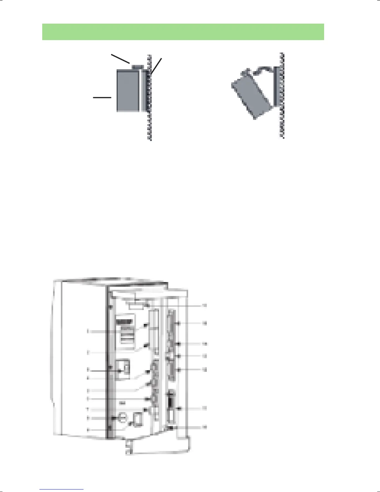
1) Open the locking mechanism
2) Open the controller slowly towards you
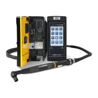
3) Connect the tool cable, power cable etc. (see picture below)
4) Connect the RBU
5) Check that the GFI (Ground Fault Interruptor) is switched on
6) Close the controller and lock it
7) Connect the power cable to a power supply (115/230 V)
8) Turn the power on
IMPORTANT! Whenever replacing a tool, always turn the power off.
Lock
Wall
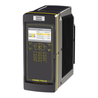
Controller
1. Digital input – Internal 24 V DC
2. Relays
3. Ground Fault Interrupter (GFI)
4. Serial #1 (RS232)
5. I/O Bus #1
6. I/O Bus #2
7. Remote start
8. Main fuse
9. Main power connector
10. Ground connection
11. Field bus card (optional)
12. RBU
13. Ethernet
14. Serial #2 (RS232)
15. Printer
16. Tool output

 Loading...