AT90S4414/8515
39
•
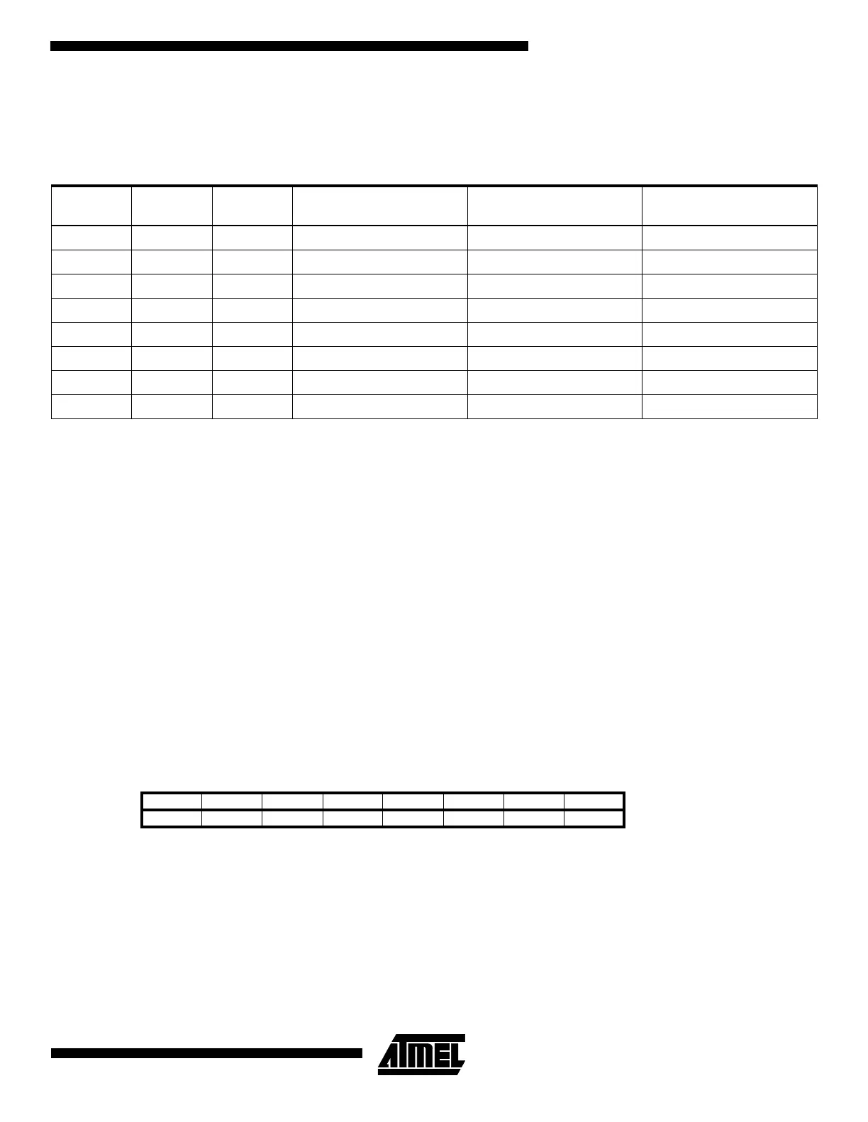
Bits 2..0 - WDP2, WDP1, WDP0: Watch Dog Timer Prescaler 2, 1 and 0
The WDP2, WDP1 and WDP0 bits determine the Watchdog Timer prescaling when the Watchdog Timer is enabled. The
different prescaling values and their corresponding Time-out Periods are shown in Table 15.
Note: The frequency of the watchdog oscillator is voltage dependent as shown in the Electrical Characteristics section.
The WDR - Watchdog Reset - instruction should always be executed before the Watchdog Timer is enabled. This ensures that
the reset period will be in accordance with the Watchdog Timer prescale settings. If the Watchdog Timer is enabled without
reset, the watchdog timer may not start to count from zero.
EEPROM Read/Write Access
The EEPROM access registers are accessible in the I/O space.
The write access time is in the range of 2.5 - 4ms, depending on the V
CC
voltages. A self-timing function, however, lets the
user software detect when the next byte can be written. If the user code contains code that writes the EEPROM, some pre-
caution must be taken. In heavily filtered power supplies, V
CC
is likely to rise or fall slowly on power-up/down. This causes
the device for some period of time to run at a voltage lower than specified as minimum for the clock frequency used. CPU
operation under these conditions is likely cause the program counter to perform unintentional jumps and eventually execute
the EEPROM write code. To secure EEPROM integrity, the user is advised to use an external under-voltage reset circuit in
this case.
In order to prevent unintentional EEPROM writes, a specific write procedure must be followed. Refer to the description of
the EEPROM Control Register for details on this.
When the EEPROM is read or written, the CPU is halted for two clock cycles before the next instruction is executed.
EEPROM Address Register - EEARH and EEARL
The EEPROM Address Registers - EEARH and EEARL specify the EEPROM address in the 512 bytes EEPROM space for
AT90S8515. For AT90S4414 EEARH is not present, thus EEARL specify the EEPROM address in the 256 bytes EEPROM
space. The EEPROM data bytes are addressed linearly between 0 and 256/512.
Table 15. Watch Dog Timer Prescale Select
WDP2 WDP1 WDP0
Number of WDT
Oscillator cycles
Typical Time-out
at V
CC
= 3.0V
Typical Time-out
at V
CC
= 5.0V
0 0 0 16K cycles 47 ms 15 ms
0 0 1 32K cycles 94 ms 30 ms
0 1 0 64K cycles 0.19 s 60 ms
0 1 1 128K cycles 0.38 s 0.12 s
1 0 0 256K cycles 0.75 s 0,24 s
1 0 1 512K cycles 1.5 s 0.49 s
1 1 0 1,024K cycles 3.0 s 0.97 s
1 1 1 2,048K cycles 6.0 s 1.9 s
Bit 151413121110 9 8
$1F ($3F) - - - - - - - EEAR8 EEARH
$1E ($3E) EEAR7 EEAR6 EEAR5 EEAR4 EEAR3 EEAR2 EEAR1 EEAR0 EEARL
76543210
Read/Write R/W R/W R/W R/W R/W R/W R/W R/W
R/W R/W R/W R/W R/W R/W R/W R/W
Initial value 8 0 0 0 0 0 0 0
80000000

 Loading...


