AT90S4414/8515
44
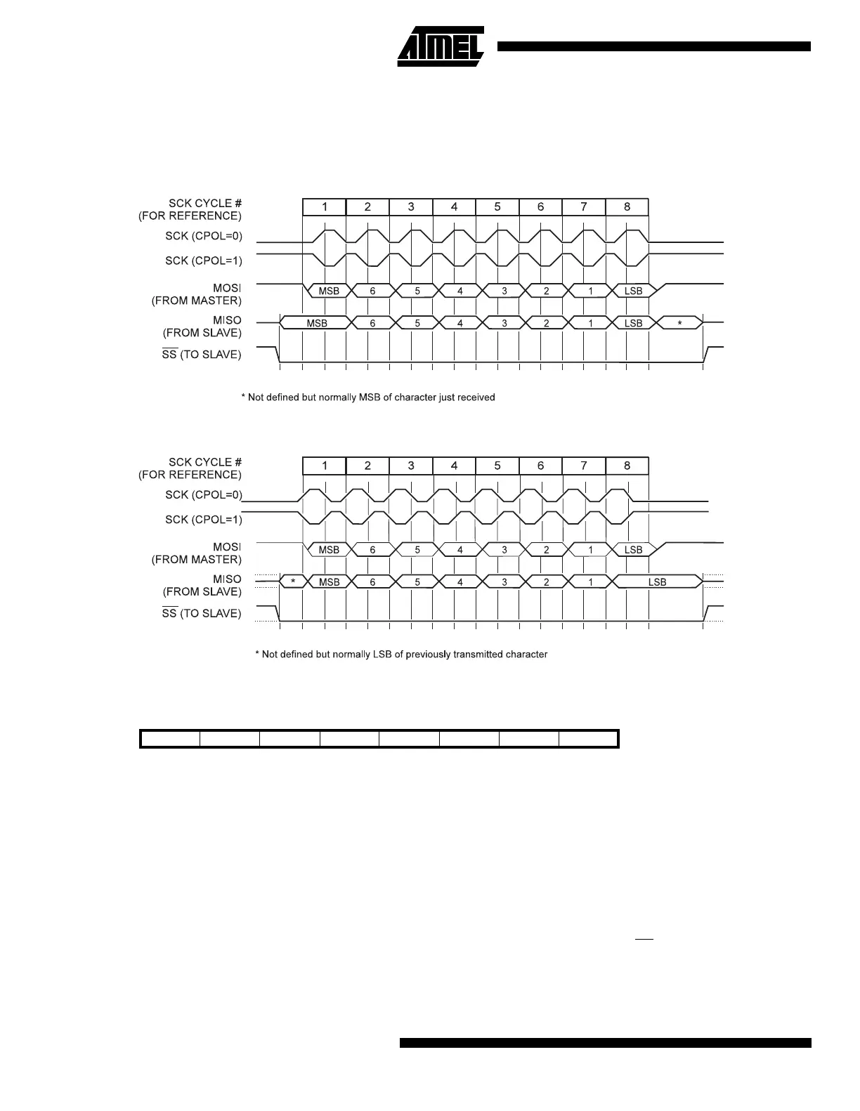
Data Modes
There are four combinations of SCK phase and polarity with respect to serial data, which are determined by control bits
CPHA and CPOL. The SPI data transfer formats are shown in Figure 36 and Figure 37.
Figure 36. SPI Transfer Format with CPHA = 0 and DORD = 0
Figure 37. SPI Transfer Format with CPHA = 1 and DORD = 0
SPI Control Register - SPCR
•
Bit 7 - SPIE: SPI Interrupt Enable
This bit causes the SPI interrupt to be executed if SPIF bit in the SPSR register is set and the global interrupts are enabled.
•
Bit 6 - SPE: SPI Enable
When the SPE bit is set (one), the SPI is enabled. This bit must be set to enable any SPI operations.
•
Bit 5 - DORD: Data Order
When the DORD bit is set (one), the LSB of the data word is transmitted first.
When the DORD bit is cleared (zero), the MSB of the data word is transmitted first.
•
Bit 4 - MSTR: Master/Slave Select
This bit selects Master SPI mode when set (one), and Slave SPI mode when cleared (zero). If SS is configured as an input
and is driven low while MSTR is set, MSTR will be cleared, and SPIF in SPSR will become set. The user will then have to
set MSTR to re-enable SPI master mode.
Bit 76543210
$0D ($2D) SPIE SPE DORD MSTR CPOL CPHA SPR1 SPR0 SPCR
Read/Write R/W R/W R/W R/W R/W R/W R/W R/W
Initial value 0 0 0 0 0 0 0 0

 Loading...


