AT90S4414/8515
53
•
Bit 2 - ACIC: Analog Comparator Input Capture Enable
When set (one), this bit enables the Input Capture function in Timer/Counter1 to be triggered by the analog comparator.
The comparator output is in this case directly connected to the Input Capture front-end logic, making the comparator utilize
the noise canceler and edge select features of the Timer/Counter1 Input Capture interrupt. When cleared (zero), no
connection between the analog comparator and the Input Capture function is given. To make the comparator trigger the
Timer/Counter1 Input Capture interrupt, the TICIE1 bit in the Timer Interrupt Mask Register (TIMSK) must be set (one).
•
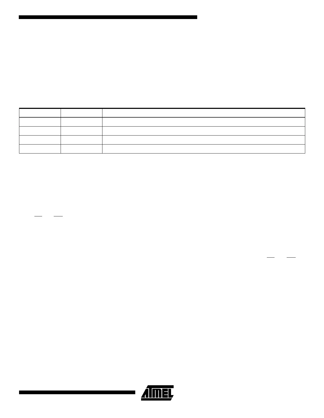
Bits 1,0 - ACIS1, ACIS0: Analog Comparator Interrupt Mode Select
These bits determine which comparator events that trigger the Analog Comparator interrupt. The different settings are
shown in Table 19.
Note: When changing the ACIS1/ACIS0 bits, The Analog Comparator Interrupt must be disabled by clearing its Interrupt Enable bit in
the ACSR register. Otherwise an interrupt can occur when the bits are changed.
Interface to External SRAM
The interface to the SRAM consists of:
• Port A: Multiplexed low-order address bus and data bus
• Port C: High-order address bus
• The ALE-pin: Address latch enable
• The RD
and WR-pin: Read and write strobes.
The external data SRAM is enabled by setting the SRE - External SRAM enable bit of the MCUCR - MCU control register,
and will override the setting of the data direction register DDRA. When the SRE bit is cleared (zero), the external data
SRAM is disabled, and the normal pin and data direction settings are used. When SRE is cleared (zero), the address space
above the internal SRAM boundary is not mapped into the internal SRAM, as in AVR parts not having interface to the
external SRAM.
When ALE goes from high to low, there is a valid address on Port A. ALE is low during a data transfer. RD
and WR are
active when accessing the external SRAM only.
When the external SRAM is enabled, the ALE signal may have short pulses when accessing the internal RAM, but the ALE
signal is stable when accessing the external SRAM.
Figure 42 sketches how to connect an external SRAM to the AVR using 8 latches which are transparent when G is high.
Default, the external SRAM access is a three-cycle scheme as depicted in Figure 43. When one extra wait state is needed
in the access cycle, set the SRW bit (one) in the MCUCR register. The resulting access scheme is shown in Figure 44. In
both cases, note that PORTA is data bus in one cycle only. As soon as the data access finishes, PORTA becomes a low
order address bus again.
For details in the timing for the SRAM interface, please refer to Figure 68, Table 38, Table 39, Table 40, and Table 41 in
section “Absolute Maximum Ratings*” on page 81.
Table 19. ACIS1/ACIS0 Settings
ACIS1 ACIS0 Interrupt Mode
0 0 Comparator Interrupt on Output Toggle
01Reserved
1 0 Comparator Interrupt on Falling Output Edge
1 1 Comparator Interrupt on Rising Output Edge

 Loading...


