Version 6.4 11 October 2011
Hardware Installation Manual 3. Physical Description
3 Physical Description
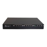
The device's chassis is an industrial platform that is 19” wide, 1U high rack-mount and 12”
deep. The device houses a single blade in Slot #1 (the lower slot - form factor 6U PICMG
2.0 single slots) on the front panel. This blade is composed of one or two identical
modules: Gateway-1 and Gateway-2, each containing 240 DSP channels. These modules
are fully independent, each possessing its own Media Access Control (MAC) and IP
address, as well as LED indicators.
This section provides a physical description of the device's front (refer to 'Front Panel' on
page 11) and rear (refer to 'Rear Panel' on page 12) panels.
3.1 Front Panel
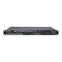
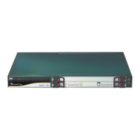
The front panel of the device is shown in the figure below and described in the subsequent
table:
Figure 3-1: Front Panel
Table 3-1: Front Panel Description
Item # Label Component Description
1 FAULT
Dual AC power LED. The device's power supply is available in
one of the following configuration options:
Single universal 100-240 VAC, 1 A max, 50-60 Hz
Dual-redundant 100-240 VAC, 1.5 A max, 50-60 Hz
-48 VDC power supply suitable for field wiring applications
For more information on this LED, see Section 3.3.7 on page
16.
2
- Blade locking screws
3
FAIL & ACT Status LEDs. For more information, see Section 3.3.1 on page
14.
4 T1/E1
STATUS
E1/T1 Trunk status LEDs (for each of the 1-8 trunks). For more
information on this LED, see Section 3.3.2 on page 14.
5
ETH (LINK &
ACT)
Ethernet LEDs. For more information on this LED, see Section
3.3.3 on page 15.
6
- Reset button
Note: This button is currently reserved for future use.
 Loading...
