Version 6.4 13 October 2011
Hardware Installation Manual 3. Physical Description
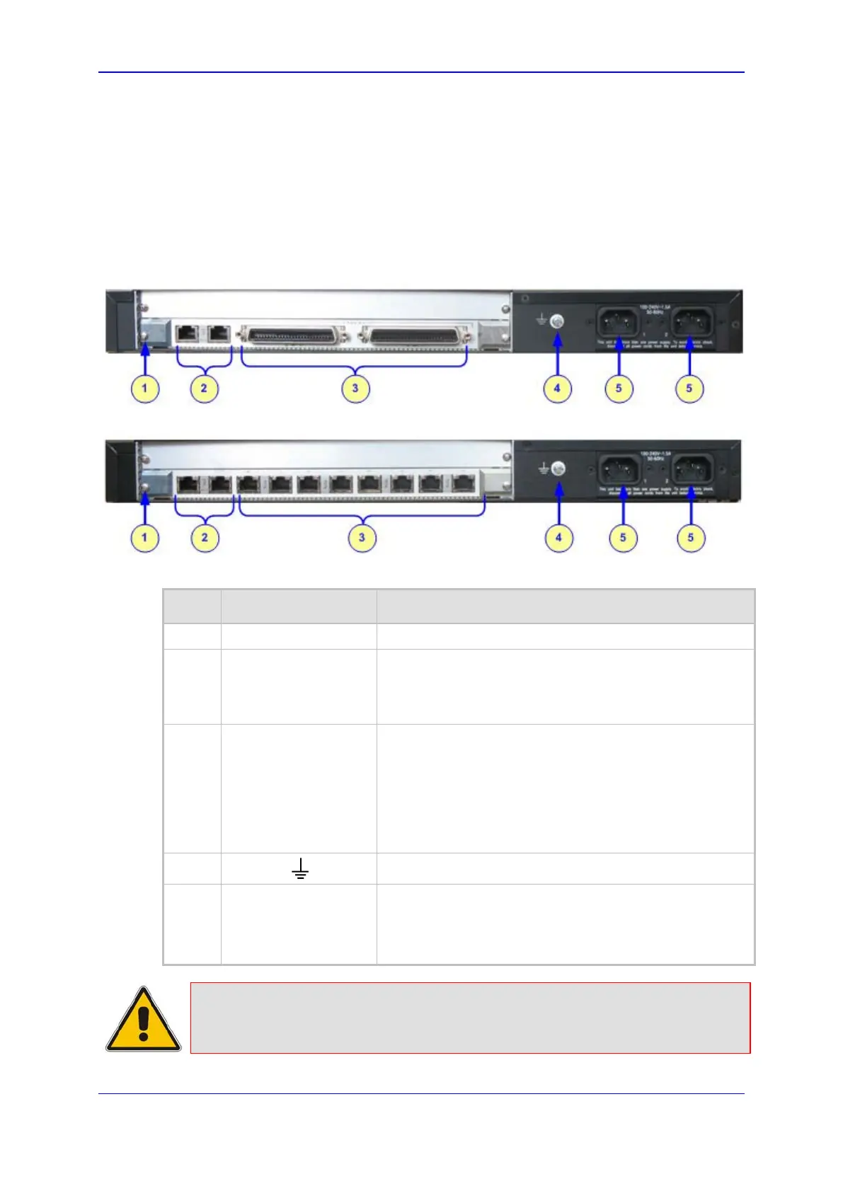
3.2 Rear Panel
The rear panel provides the port interfaces such as E1/T1 PSTN, Ethernet (IP), and power.
The PSTN and Ethernet port interfaces are provided by a single Rear Transition Module
(RTM-1610) in Slot #1 (the lower slot).
The rear panel design depends on the number of supported trunks and the type of power
(AC or DC), as shown in the figures below:
Figure 3-2: RTM-1610 for 16 Trunks (and AC Power)
Figure 3-3: RTM-1610 for 8 Trunks (and AC Power)
Table 3-2: Rear Panel Description
Item # Label Component Description
1
- RTM locking screws (or RTM latches).
2 ETH
Two 10/100Base-TX, RJ-45 shielded ports. This dual
Ethernet interface provides an Ethernet redundancy
scheme (active/standby), offering protection against
Ethernet failure.
3
TRUNKS (16 spans)
-or-
PSTN (1, 2, 4, or 8
spans)
The connector depends on the number of required
spans:
16 Spans: Two 50-pin female Telco connector (DDK
57AE-40500-21D) for E1/T1 trunks 1 to 8, and 9 to 16
respectively.
1, 2, 4, or 8 Spans: Up to eight RJ-48c ports, each
supporting an E1/T1 trunk.
4
Protective earthing screw.
5 100-240~1.5A
or 48V 4A max
One of the following power interfaces (depending on
customer requirements):
Dual AC power sockets
2-Pin DC connector
Note: The RS-232 interface port is available for blades supporting 1-, 2-, and 4-
span configurations.

 Loading...


