3 MP-124 Hardware Installation
This chapter describes the MP-124 hardware installation.
3.1 Physical Description
The subsections below provide a physical description of the MP-124 front and rear panels.
3.1.1 MP-124 Front Panel
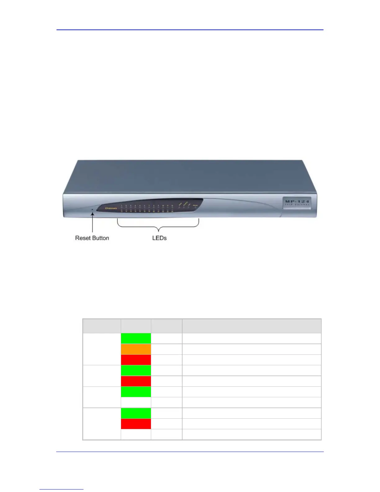
The MP-124 front panel, shown in the figure below provides LEDs for indicating various
operating statuses, and a reset button.
Figure 3-1: MP-124 Front Panel
3.1.1.1 Reset Pinhole Button
The MP-124 reset pinhole button enables you to reset the device or restore the device to
factory default settings. For more information, refer to the User's Manual.
3.1.1.2 LEDs Description
The MP-124 LEDs are described in the table below.
Table 3-1: MP-124 Front-Panel LEDs Description
Label Color State Function
Ready
Green On Device powered on, self-test OK.
Orange Blinking Software loading/initialization.
Red On Malfunction.
LAN
Green On Valid 10/100Base-TX Ethernet connection.
Red On Malfunction.
Control
Green Blinking Sending and receiving SIP messages.
- Off No traffic.
Data
Green Blinking Transmitting RTP packets.
Red Blinking Receiving RTP packets.
- Off No traffic.

 Loading...