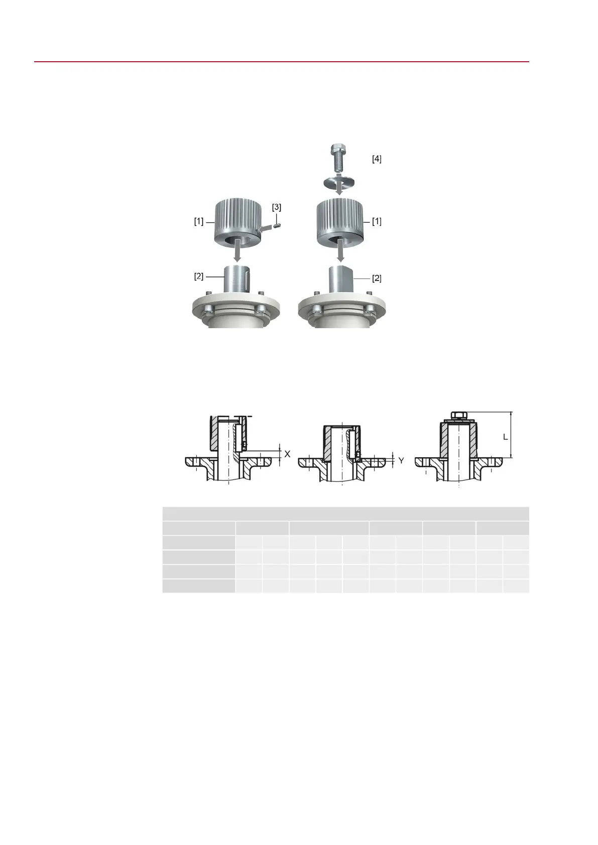
4. Place coupling [1] onto valve shaft [2] and secure against axial slipping by using
a grub screw [3] or a clamping washer and a screw with curved spring lock
washer [4].Thereby, ensure that dimensions X, Y or L are observed (refer to
figure and table <Mounting positions for coupling>).
Figure 12: Examples: Fit coupling
[1] Coupling
[2] Valve shaft
[3] Grub screw
[4] Clamping washer and screw with curved spring lock washer
Figure 13: Mounting positions for coupling
Table 8:
Mounting position of the coupling within fitting dimensions according to AUMA definition
SQ 14.2SQ 12.2SQ 10.2SQ 07.2SQ 05.2Dimensions [mm]
F16F14F14F12F12F10F10F07F05F07F05EN ISO 5211
88554433333X max.
101010105522222Y max.
125751016182506640404040L max.
5. Apply non-acidic grease at splines of coupling (e.g. Gleitmo by Fuchs).
18
SQ 05.2 – SQ 14.2/SQR 05.2 – SQR 14.2 Control unit: electronic (MWG)
Assembly AC 01.2 Non-Intrusive

 Loading...