5.2. Electrical connection
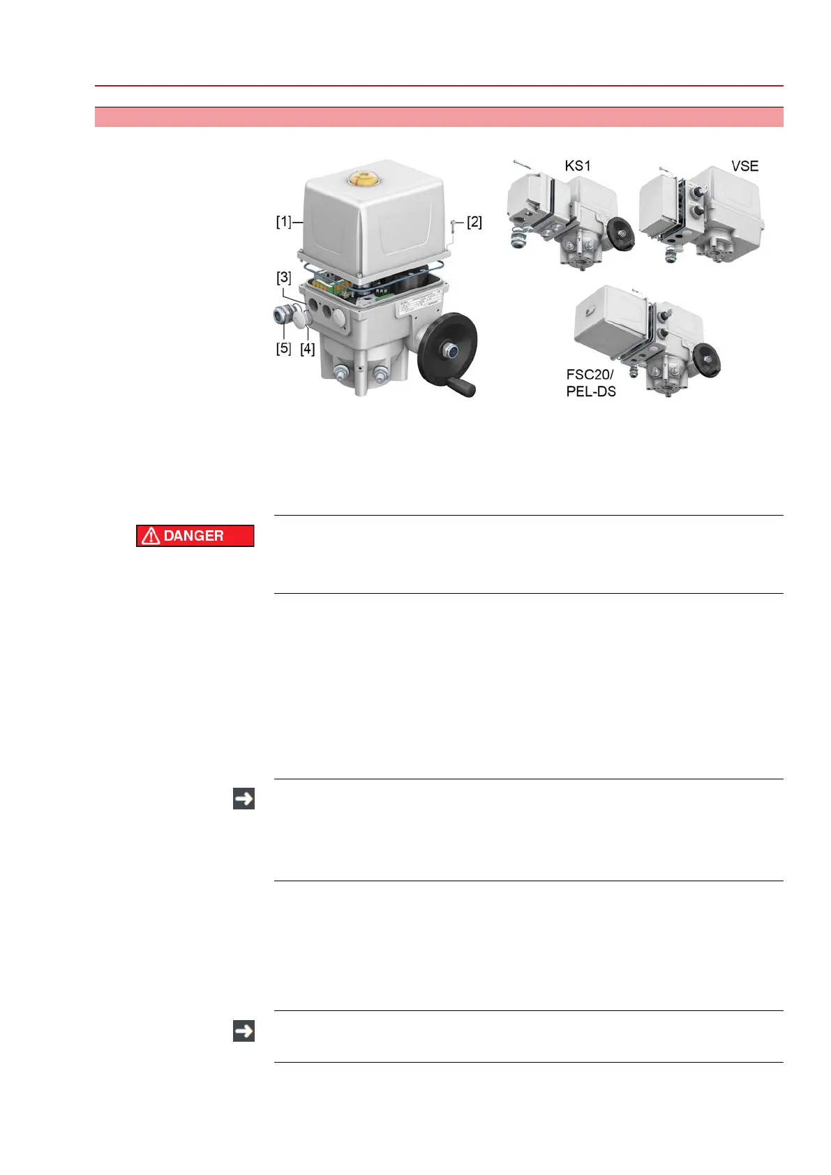
Figure 9: Electrical connection in standard version and product variants
[1] Hood
[2] Screws at actuator housing
[3] Cable entry
[4] Blanking plug
[5] Cable gland (not included in scope of delivery)
Electric shock due to presence of hazardous voltage!
Failure to observe this warning results in death or serious injury.
→
Disconnect device from the mains before opening.
1. Open terminal compartment:
1.1 For standard version: Loosen screws [2] and remove hood [1] at the actu-
ator housing.
1.2 For KS1, VSE and FSC20/PEL-DS product variants, remove the laterally
mounted cover or hood. The hood [1] may remain closed.
2. Remove available blanking plugs [4].
3. Insert cable glands [5] suitable for connecting cables.
4. Seal unused cable entries [3] with suitable blanking plugs [4].
The enclosure protection stated on the name plate IP... is only ensured if cable
glands and blanking plugs are used which are appropriate for the specified
enclosure protection. For use in potentially explosive atmospheres, only cable
glands and blanking plugs approved for the respective type of protection may
be used.
5. Remove cable and wire sheathing.
6. For flexible cables: Use wire end sleeves according to DIN 46228.
7. Connect cable according to order-related wiring diagram.
8. Fasten cable glands with the torque as specified by the manufacturer to ensure
respect of required enclosure protection.
9. Place hood [1] or cover and fasten screws evenly crosswise.
If commissioning is directly performed following electrical connection: Leave
hood [1] open!
13
EQ 40 – EQ 150
EQ 300 – EQ 600 Electrical connection