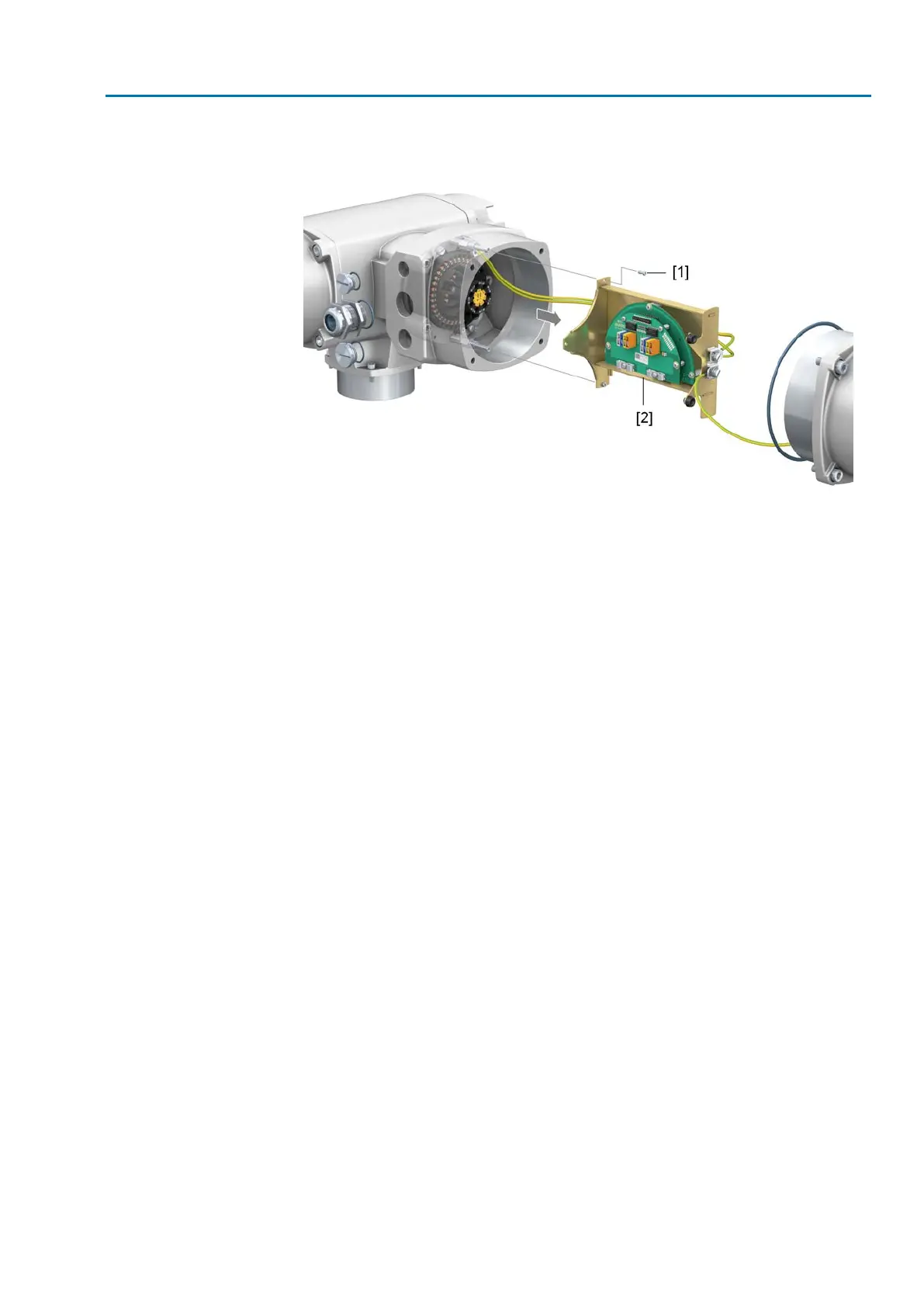
Figure 22: Disassembly of mounting frame
[1] Screws
[2] Mounting frame with connection board
1. Loosen screws [1] and remove mounting frame [2].
How to proceed
2. Remove cable sheathing in a length of 250 – 300 mm.
3. Insert the wires into the cable glands.
4. Fasten cable glands with the specified torque to ensure required enclosure
protection.
Information: For shielded cables: Link the cable shield end via the cable gland
to the housing (earthing).
5. Strip wires:
5.1 Remove wire sheathing of control cables (1...50) in a length of approx. 10
mm
5.2 Remove wire sheathing of motor cables (U,V,W) in a length of approx.
12 mm
6. For flexible cables: Use wire end sleeves according to DIN 46228. For spring
clamp terminals, connection is also possible without wire end sleeves.
Information: For two flexible wires per terminal, a joint wire end sleeve must
be used (twin wire end sleeve).
31
SAEx 07.2 – SAEx 16.2 / SAREx 07.2 – SAREx 16.2 Control unit: electronic (MWG)
ACExC 01.2 Non-Intrusive Profinet Electrical connection
 Loading...