How to proceed
Electric shock due to presence of hazardous voltage!
Failure to observe this warning results in death or serious injury.
→
Disconnect device from the mains before opening.
1. Loosen screws [2] and remove cover [1].
2. Insert cable glands suitable for connecting cables.
Information: When selecting cable glands, observe type of protection (with
Ex e or Ex d approval) and enclosure protection IP (refer to name plate).
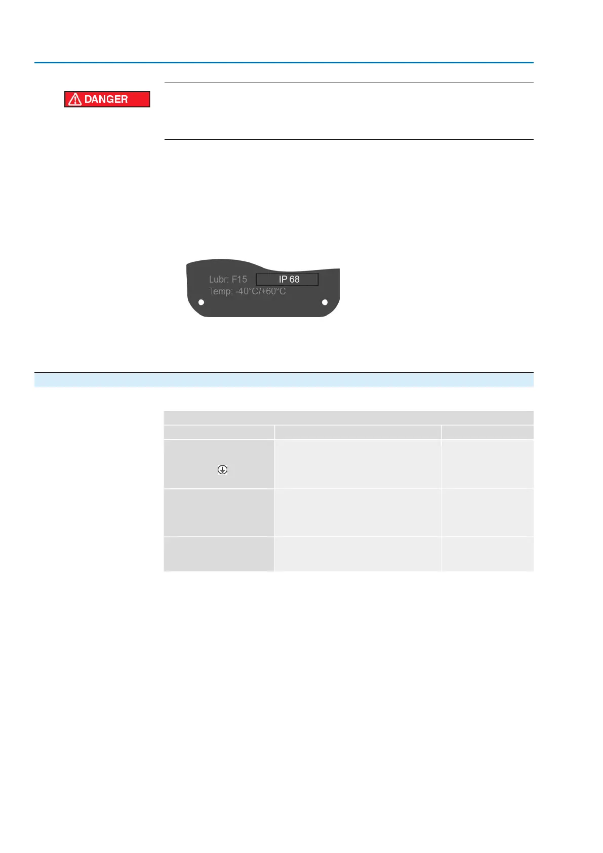
The enclosure protection stated on the name plate IP is only ensured if suitable
cable glands are used.Thread types and thread sizes are specified on the
approval plate in explosion-proof version. Refer to chapter <Identification/name
plate>.
Figure 21: Name plate, example with enclosure protection IP68
Information: For shielded cables: Use EMC cable glands.
3. Seal unused cable entries with approved plugs suitable for the required protec-
tion type.
5.2.2. Cable connection
Table 18:
Terminal cross sections and tightening torques
Connection typeTerminal cross sectionsDesignation
Screw-type terminals
Tightening torque =
1.2 – 1.5 Nm
Flexible or solid:
0.25 – 10.0 mm
2
(for one wire per terminal)
Flexible:
2 x 0.25 – 4 mm
2
(for two wires per terminal)
Power contacts
(U1, V1, W1, U2, V2, W2)
PE connection
Spring clamp terminalsFlexible or solid:
0.25 – 2.5 mm
2
(for one wire per terminal)
2 x 0.25 – 0.75 mm
2
(for two wires per termin-
al)
Control contacts
(1 to 36, 37 to 50)
Ring lug/U-bracket
Tightening torque = 3 – 4
Nm
2 x M6 for cables with M6 ring lug or with U-
bracket for up to two wires with
1.5 mm
2
– 10 mm
2
Protective earth connection
within frame (customer connec-
tion)
30
SAEx 07.2 – SAEx 16.2 / SAREx 07.2 – SAREx 16.2 Control unit: electronic (MWG)
Electrical connection ACExC 01.2 Non-Intrusive Profinet
 Loading...