with small clamp washers1)
1. Remove cable sheathing in a length of 120 – 140 mm.
2. Strip wires.
→
Controls max. 8 mm, motor 12 mm
3. For flexible cables: Use end sleeves according to DIN 46228.
4. Connect cables according to order-related wiring diagram.
Information: Two wires for each connection permitted.
→
When using motor cables with a cross section of 1.5 mm²: Use small clamp
washers for connection to terminals U1, V1, W1 and PE (the small clamp
washers are provided in the electrical connection cover).
In case of a fault: Hazardous voltage while protective earth conductor is NOT
connected!
Risk of electric shock.
→
Connect all protective earth conductors.
→
Connect PE connection to external protective earth conductor of connecting
cables.
→
Start running the device only after having connected the protective earth con-
ductor.
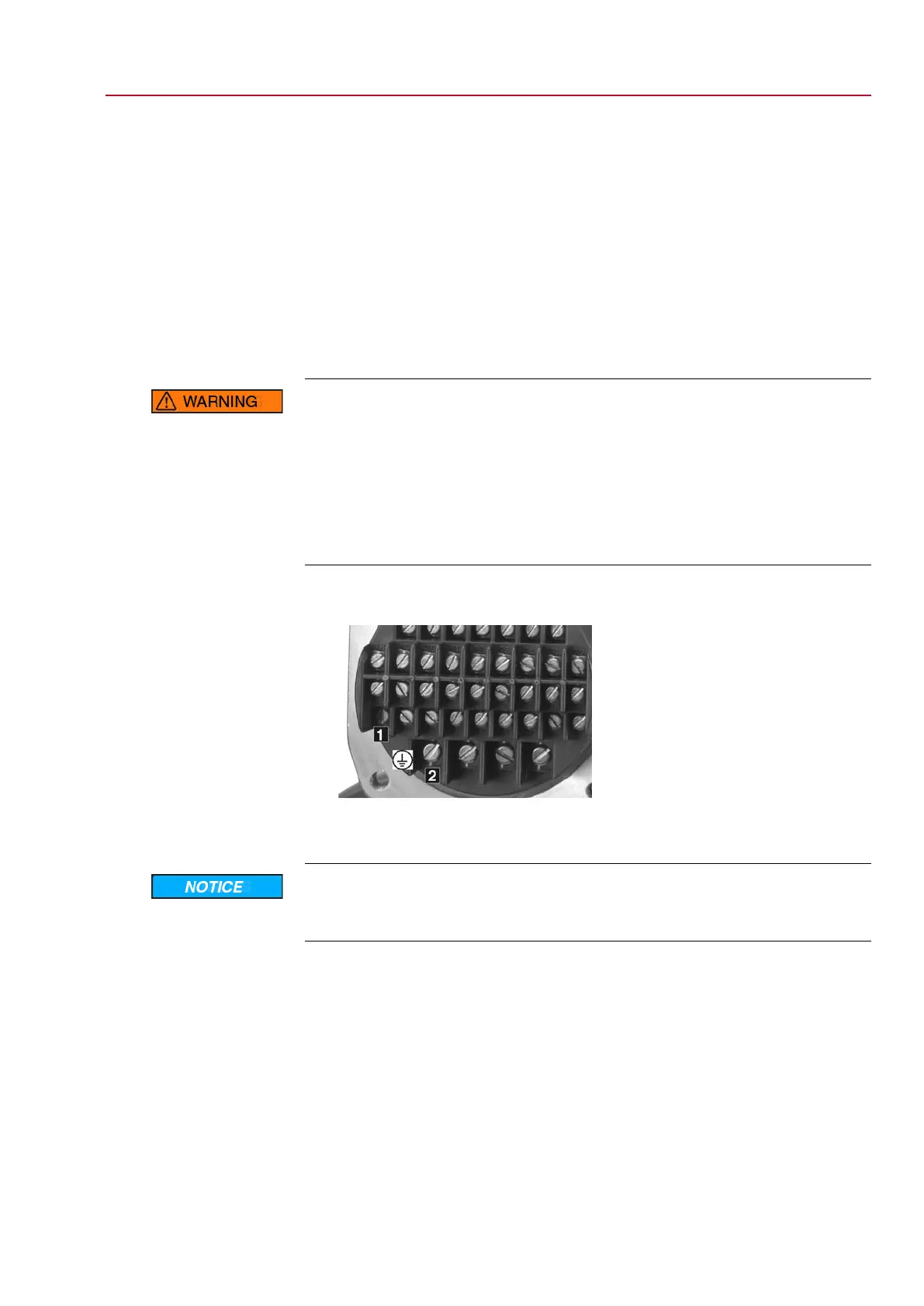
5. Tighten protective earth firmly to PE connection
Figure 13: PE connection
[1] PE connection, control cable
[2] PE connection, motor cable
Danger of corrosion: Damage due to condensation!
→
After mounting, commission the device immediately to ensure that heater mini-
mises condensation.
Information Some actuators are equipped with an additional motor heater. The motor heater
minimises condensation within the motor and improves the start-up behaviour for
extremely low temperatures.
19
SGExC 05.1 – SGExC 12.1 Control unit: electromechanic
ACExC 01.2 Intrusive Modbus RTU Electrical connection

 Loading...


