Flameproof enclosure, danger of explosion!
Risk of death or serious injury.
→
Handle cover and housing parts with care.
→
Joint surfaces must not be damaged or soiled in any way.
→
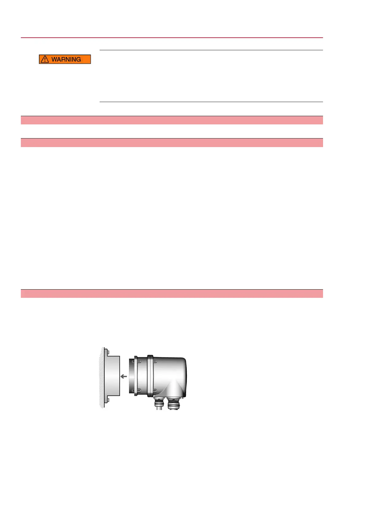
Do not jam cover during fitting.
5. Fit cover [1] and fasten screws [2] evenly crosswise.
5.4 Accessories for electrical connection
— Option —
5.4.1 Controls mounted to wall bracket
The wall bracket allows separate mounting of controls and actuator.
Application
●
If the actuator cannot be accessed.
●
If the actuator is subjected to high temperatures.
●
In case of heavy vibration of the valve.
Design
Observe prior to
connection
●
Permissible length of connecting cables: max. 100 m.
●
If the actuator is equipped with a position transmitter (RWG): Connecting cables
must be available as shielded version.
●
Versions with potentiometer in the actuator are not suitable.
●
We recommend: AUMA cable sets LSW8-KES or LSW9-KP.
●
If the AUMA cable set is not used: Use suitable flexible and screened connecting
cables.
●
When using connecting cables, e.g. of the heater or switch, requiring direct wiring
from the actuator to the XK customer connector (XA-XM-XK, refer to wiring
diagram), these connecting cables must be subject to an insulation test in
compliance with EN 50178. Connecting cables of position transmitters (RWG,
IWG, potentiometer) do not belong to this group.They may not be subject to
an insulation test.
5.4.2 Parking frame
Application
Parking frame for safe storage of a disconnected plug.
For protection against touching the bare contacts and against environmental
influences.
Figure 23: Parking frame and plug/socket connector with screw-type terminals
(KP/KPH)
26
SGExC 05.1 – SGExC 12.1 Control unit: electromechanic
Electrical connection ACExC 01.2 Intrusive Modbus RTU

 Loading...


