4. Assembly
4.1. Mounting position
The product described in this document can be operated in any mounting position.
Restriction: When using oil instead of grease within the actuator gear housing, the
hollow shaft mounting position must be perpendicular, with the flange pointing
downward.The type of lubricant used is indicated on the actuator name plate (short
designation F...= grease; O...= oil).
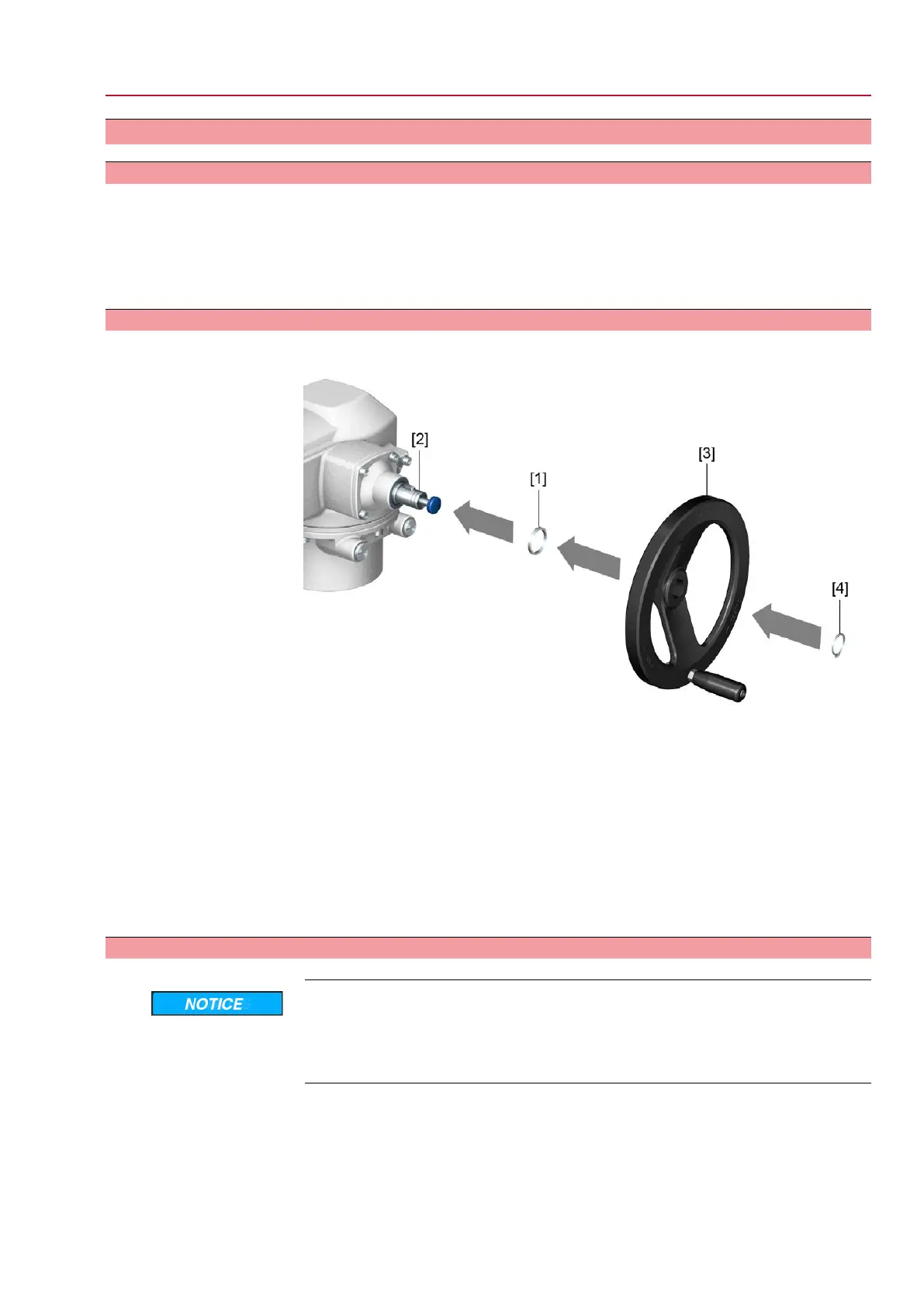
4.2. Handwheel fitting
Figure 8: Handwheel
[1] Spacer
[2] Input shaft
[3] Handwheel
[4] Retaining ring
1. If required, fit spacer [1] onto input shaft [2].
2. Slip handwheel [3] onto input shaft.
3. Secure handwheel [3] using the retaining ring [4] supplied.
Information
The retaining ring [4] (together with these operation instructions) is stored in a
weatherproof bag, which is attached to the device prior to delivery.
4.3. Part-turn actuator to valve: mount
Danger of corrosion due to damage to paint finish and condensation!
→
Touch up damage to paint finish after work on the device.
→
After mounting, connect the device immediately to electrical mains to ensure
that heater minimises condensation.
The part-turn actuator is mounted to the valve using a coupling (standard) or via
lever. Separate instructions are available for actuator mounting to the valve when
equipped with base and lever.
15
SQ 05.2 – SQ 14.2 / SQR 05.2 – SQR 14.2 Control unit - electromechanical
AC 01.2 Intrusive Modbus RTU Assembly

 Loading...


