2. If the actuator is the final fieldbus device in the fieldbus segment:
2.1 Switch on the termination resistor for channel 1 using switch [S1] (position
ON).
2.2 For line redundancy: Switch on the termination resistor for channel 2 using
switch [S2] (position ON).
Information: As soon as the termination resistors are switched on, the
connection to the next fieldbus device is automatically interrupted to avoid
multiple terminations.
3. Connect cable shield largely to shielding clamp [X].
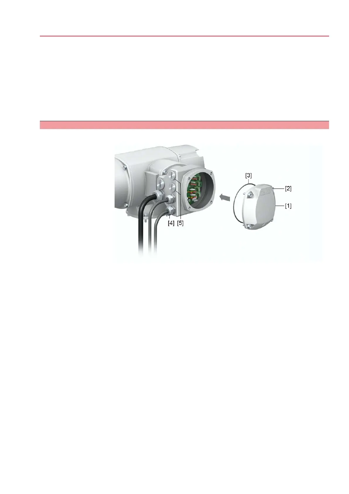
5.2.6. Fieldbus terminal compartment: close
Figure 23: Close fieldbus terminal compartment
[1] Cover (fieldbus terminal compartment)
[2] Screws for cover
[3] O-ring
[4] Cable entries for fieldbus cables
[5] Blanking plug
1. Clean sealing faces of cover [1] and housing.
2. Apply a thin film of non-acidic grease (e.g. petroleum jelly) to the sealing faces.
3. Check whether O-ring [3] is in good condition, correctly insert O-ring.
4. Fit cover [1] and fasten screws [2] evenly crosswise.
5. Fasten cable glands and blanking plugs applying the specified torque to ensure
the required enclosure protection.
29
SQ 05.2 – SQ 14.2 / SQR 05.2 – SQR 14.2 Control unit - electromechanical
AC 01.2 Intrusive Modbus RTU Electrical connection

 Loading...


