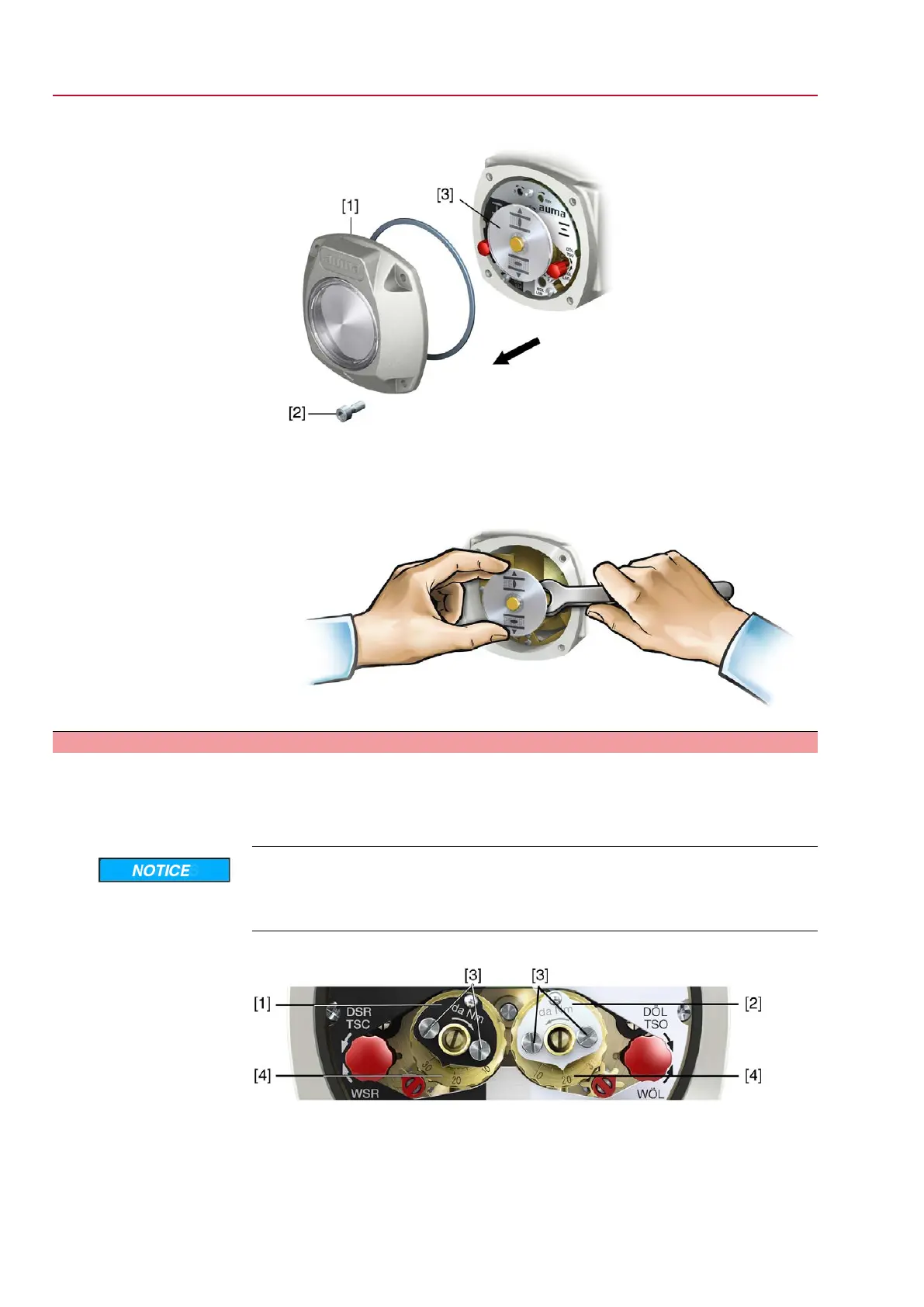
1. Loosen screws [2] and remove cover [1] from the switch compartment.
2. If indicator disc [3] is available:
Remove indicator disc [3] using a spanner (as lever).
Information: To avoid damage to paint finish, use spanner in combination with
soft object, e.g. fabric.
9.5. Torque switching: set
Once the set torque is reached, the torque switches will be tripped (overload protection
of the valve).
Information The torque switches may also trip during manual operation.
Valve damage due to excessive tripping torque limit setting!
→
The tripping torque must suit the valve.
→
Only change the setting with the consent of the valve manufacturer.
Figure 59: Torque measuring heads
[1] Torque switching head black in direction CLOSE
[2] Torque switching head white in direction OPEN
[3] Lock screws
[4] Torque dials
1. Loosen both lock screws [3] at the indicator disc.
54
SQ 05.2 – SQ 14.2 / SQR 05.2 – SQR 14.2 Control unit - electromechanical
Commissioning (basic settings) AC 01.2 Intrusive Modbus RTU

 Loading...


