5.2.1. Terminal compartment (for mains connection): open
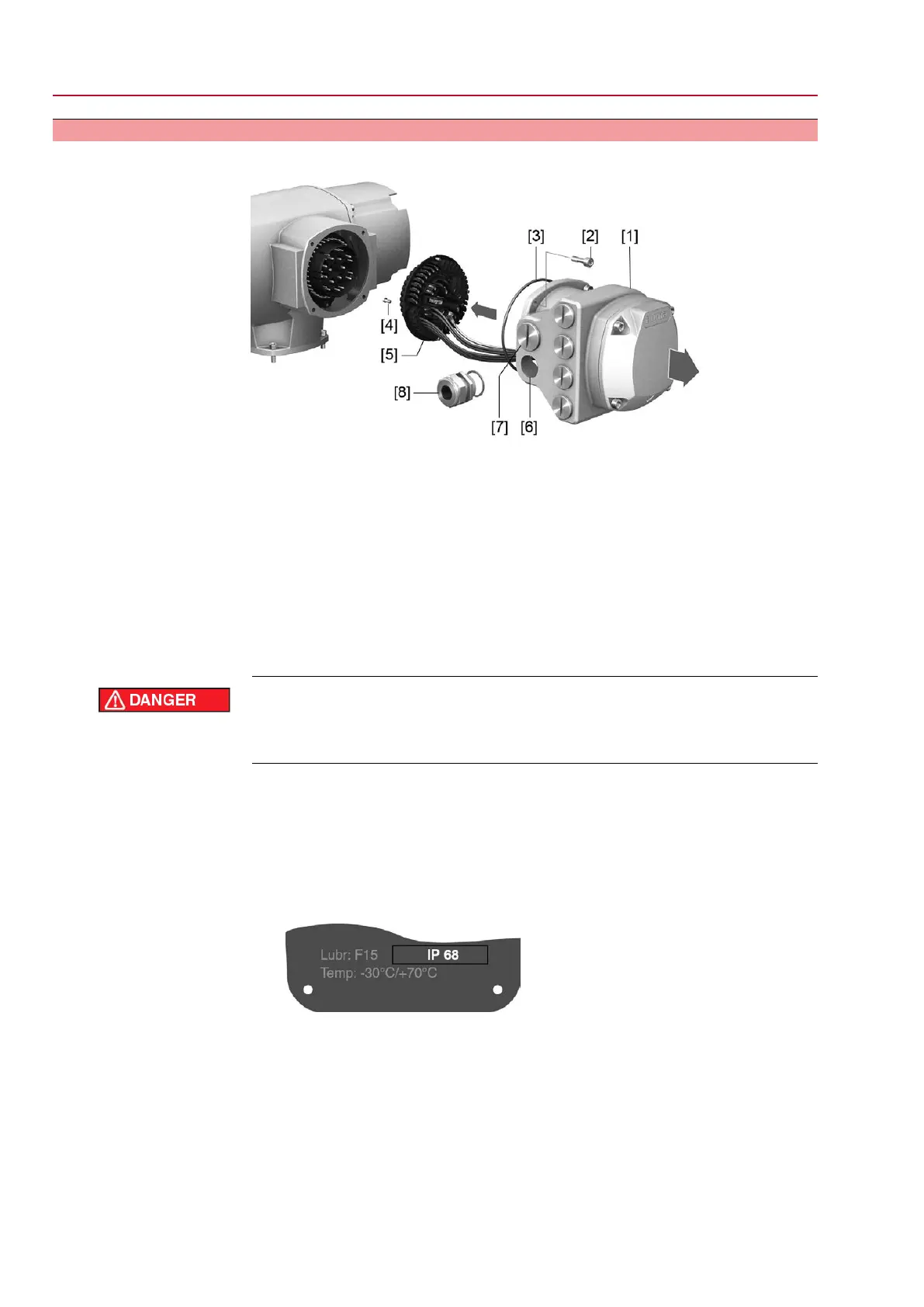
Figure 16: Open mains terminal compartment
[1] Connection housing
[2] Screws for frame
[3] O-ring
[4] Screws for socket carrier
[5] Socket carrier
[6] Cable entries for mains connection (power and control contacts)
[7] Blanking plug
[8] Cable gland (not included in delivery)
Information Fieldbus operation is not interrupted when removing the connection housing [1].
Hazardous voltage!
Risk of electric shock.
→
Disconnect device from the mains before opening.
1. Loosen screws [2] and remove connection housing [1].
2. Loosen screws [4] and remove socket carrier [5] from connection housing [1].
3. Insert cable glands [8] suitable for connecting cables.
➥
The enclosure protection IP… stated on the name plate is only ensured if suit-
able cable glands are used.
Figure 17: Example: Name plate for enclosure protection IP68
4. Seal unused cable entries [6] with suitable blanking plugs [7].
Information
Fieldbus connection can be accessed separately from the mains connection (refer
to <Fieldbus terminal compartment: open>.
24
SQ 05.2 – SQ 14.2 / SQR 05.2 – SQR 14.2 Control unit - electromechanical
Electrical connection AC 01.2 Intrusive Modbus RTU

 Loading...


